


7
Assembly
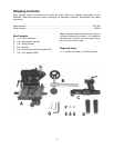
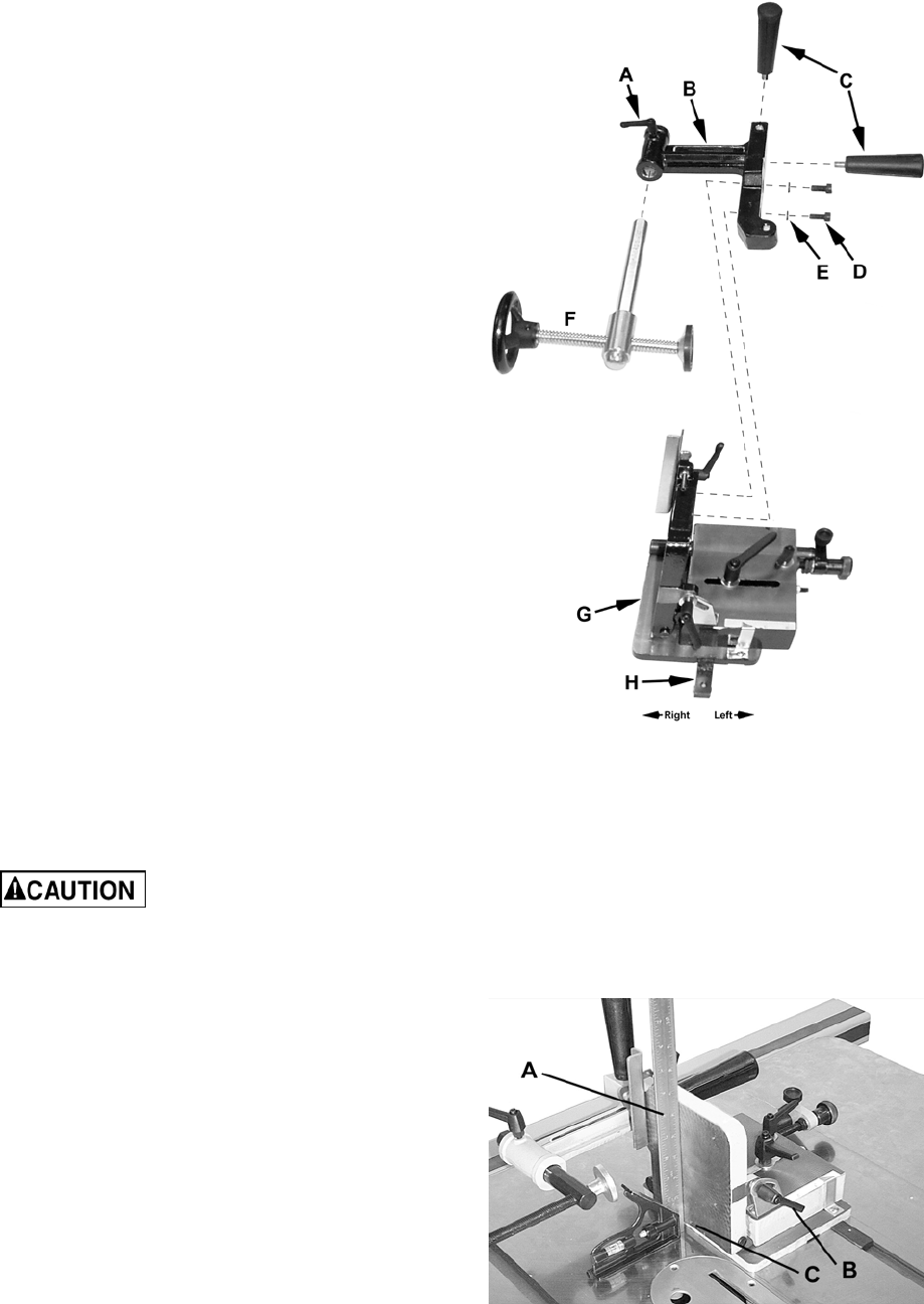
Refer to Figure 1.
1. Insert the handwheel assembly (F) into the
clamp bracket (B) and secure with the lock
handle (A) on the clamp bracket.
2. Attach the clamp bracket (B) to the back of
the fence (G) using two M10 x 25 socket head
cap screws (D) and M10 lock washers (E).
3. Attach the handles (C) to the clamp
bracket (B).
Note: There are two slots on the underside of the
tenoning jig. For the JTSA-10XL, 66 and 64A JET
& Powermatic left tilt saws, mount the slide (H)
into the left slot (farthest from the fence). A 4 mm
hex wrench (provided) is required.
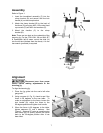
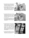
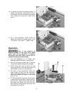
Alignment
Disconnect saw from power
source before making adjustments to the
tenoning jig.
To align the tenoning jig:
1. Place the jig guide into the saw's left miter
gauge slot.
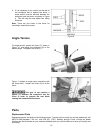
2. Using a square (A, Fig. 2), check to see if the
fence is 90 degrees to the saw table. To
make an adjustment to the fence, loosen the
lock handle (B), adjust the fence to the
90-degree position and tighten lock handle.
3. When the fence is 90 degrees to the table,
tighten setscrew (C) until it bottoms. See
Figure 2. Setscrew (C) acts as a positive stop
and allows you to quickly position the fence
back to the 90-degree position after it has
been tilted.
Figure 1
Figure 2