


5
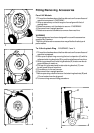
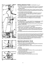
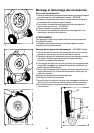
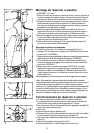
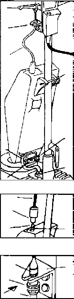
Fitting Solution Tank - DIAGRAMS 5, 6 and 7
1 Remove three plastic covers and screws at rear of chrome motor
cover. Firmly anchor mounting block (G) in position using three
screws provided.
2 Align slots in bracket (D) with inserts in side of machine handle.
Using two screws provided lightly clamp bracket into position. Do
not fully tighten bracket at this stage.
3 Locate lower tank mounting bracket over block (G) on chrome
cover and secure by pushing retaining pin (B) through both
sections until locked.
4 Locate upper bracket around machine handle shaft and secure by
pushing retaining pin (A) through both sections until locked.
5 Connect plastic tube (C) to feed point (F) on machine base.
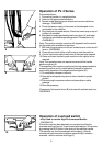
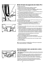
To fit Control Cable
6 Screw connector (J) of control cable (H) onto tank plunger rod (K)
and HAND tighten against fixed locknut (L) - DIAGRAM 6.
7 Slide cable loop over left hand flow control lever (E) and locate in
groove - DIAGRAM 5.
8 Slide bush (M) on control cable (H) into slot in bracket (D) and
tighten hand nut (N) to secure - DIAGRAM 7.
9 With handle in the UPRIGHT position, lightly push bracket (D)
down until any free play in control cable (H) is eliminated. Firmly
tighten bracket screws and cover screw heads with snap caps
provided.
Do not apply excessive force when adjusting bracket for free play.
Note: If your machine does not have locating holes in side Of handle
or at rear of chrome motor cover to enable fixing of either the cable
bracket (D) or tank mounting block (G) please ring 01242 243421
and specify the model name shown on the motor cover label and the
serial number stamped on the serial plate located on the base
casting underneath the handle pivot.
Operating Solution Tank
1 Always fill solution tank in upright position.
2 The useful capacity of the tank for calculating dilution rates when
mixing cleaning solution is 11 litres.
3 To operate, gently raise flow control lever (E) whilst machine is
running.
4 To empty:
a. Disconnect plastic tube (C).
b. Unscrew hand nut (N) and slide bush (M) on control cable (H)
from slot in bracket (D).
c. Slide cable loop from flow control lever (E).
d. Remove retaining pins (A) and (B).
e. Unscrew cap, pour out cleaning solution then rinse.
5
6
7
E
D
H
A
B
C
F
G
H
J
K
L
M
N
D
H