


Python
®
Lincoln Compatible
™
Owner's Manual - Page 2
Controls and Settings
Potentiometer
The laterally-positioned potentiometer is located in the lower end of the
handle, providing up to 800 ipm with 3 3/4 turns.
Micro Switch
The micro switch assembly consists of the micro switch, and leads.
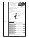
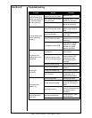
Trigger Sensitivity
The amount of trigger level travel can
be shortened for a "quicker" or "more
responsive" action.
A more sensitive trigger lever is produced
by reducing the gap between the
trigger lever and the micro-switch lever.
By turning-in the Trigger Sensitivity
Adjustment Screw, it closed the gap
between the trigger lever and the micro-
switch lever.
This well enable the operator to increase
the sensitivity of the trigger lever.
Sensitivity Adjustment
With the wire feeder turned on (with
or without welding wire loaded), turn
the screw in until the micro-switch is
activated. Once activated, the gun and
wire feeder motors will begin feeding wire.
Retract the screw accordingly until the
system is deactivated and adjusted to the
operators' liking.
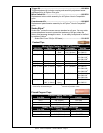
Drive Roll and Idler Rolls
General
The Python
®
Lincoln Compatible
™
gun comes standard with a knurled drive
roll and a grooved idler roll, which will handle both steel and aluminum wire
with diameters from .030-1/16 inch. Optional insulated V-groove drive rolls
are also available for aluminum wire if desired (see Optional Kits).
Drive roll tension is accomplished with a unique spring-loaded pressure
screw. The Python
®
Lincoln Compatible
™
comes from the factory with
the pressure adjustment screw preset. NO ADJUSTMENT IS
REQUIRED FOR ALL SIZES AND TYPES OF WIRES.
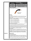
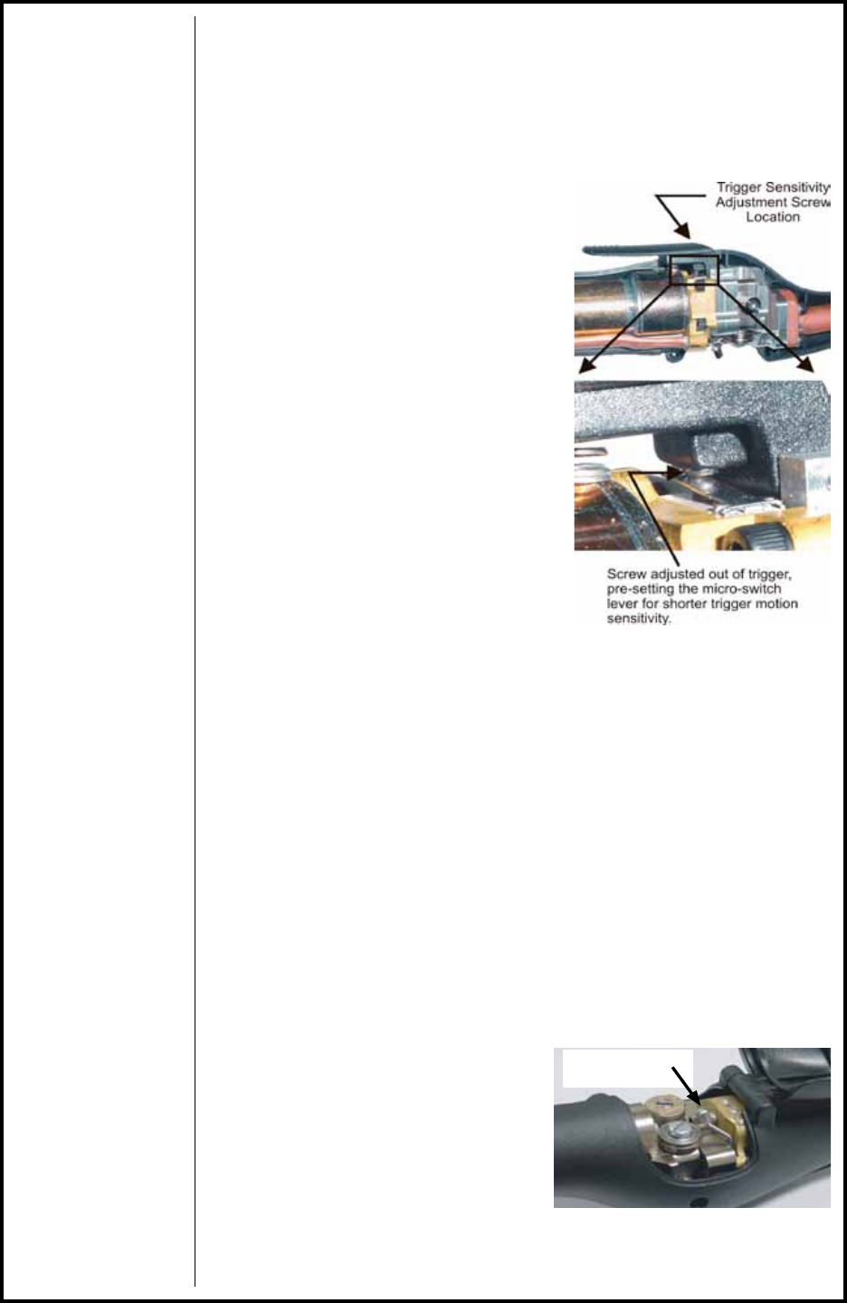
Drive Roll Installation/Removal
NOTE: Neither of the handles needs to be removed to access the Drive
or Idler Rolls.
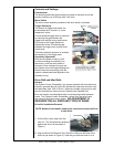
1. Pull the Cam Lever away from the
idler roll. This will relieve the pressure
against the drive roll (as shown in
Figure 1).
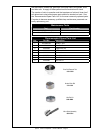
2. Align the Drive Roll Removal Tool (P/N 931-0100) over the ats of the
drive roll (as shown in Figure 2). Hold the gun with one hand or on a
Cam Lever
Figure 1