


5
Step 3. Mount the Router
Place the router on a flat surface, mount it in a standard 19-inch Electronic Industries Association (EIA) rack, or mount
it on the optionally available shelf.
Step 4. Install the SFP Transceivers
An SFP transceiver is required for each of the router’s Fibre Channel ports that will be connected to a Fibre Channel
device or switch. The iSR6152 Router package contains two SFPs.
To install an SFP transceiver, insert the transceiver into the router port, and then press gently until it snaps in place. The
transceiver will fit only one way. If the transceiver does not install under gentle pressure, flip it over and try again.
Step 5. Apply Power to the Router
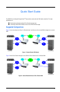
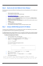
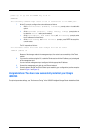
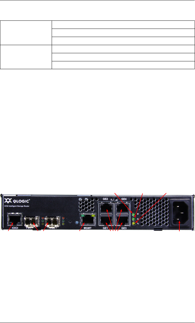
Figure 3 shows the location of the ports and LEDs on the iSR6152 Router.
Figure 3. iSR6152 Ports and LEDs
1. Attach the AC power cord to the iSR6152 Router, and then to the wall outlet or power strip.
2. Verify that the router’s input power LED is illuminated.
The iSR6152 Router first runs its self-test, which takes about one minute, and then begins normal
operation.
3. Verify that the heartbeat LED is blinking (once per second) and that the system fault LED is not
illuminated.
For installation details, diagnostics, and troubleshooting, see the iSR6152 Intelligent Storage Router Installation Guide.
GbE Port 3 (GE3)
IP Address:
Subnet Mask:
Gateway:
GbE Port 4 (GE4)
IP Address:
Subnet Mask:
Gateway:
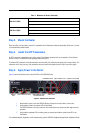
Table 1. Worksheet for Router (Continued)
AC PowerGbE PortsManagement Port
10/100 Ethernet
Input Power LEDHeartbeat LED System Fault LED
Fibre Channel PortsRS232
Port