DN1 • 13
11. Install R1, 1K ohm [brown-black-red].
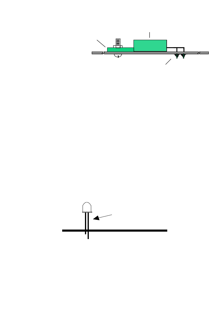
11. Install Q1, the power FET transistor [marked 7035]. Form the leads
as shown prior to
installation. Bolt the
regulator to the circuit
board.
12. Install L1, the large
axial leaded wire wound
inductor.
13. Install D1, 1N4937 fast
recovery diode. Observe the correct polarity! Note also that this is
another “stand up” diode, so form the leads as before for a proper fit.
14. Identify Q2, a 2N3904 NPN transistor. When installing Q2, observe
correct placement of the flat side. Press the transistor snugly into the
PC board so that only a minimum amount of wire lead is exposed above
the board. In soldering, do not be afraid of using enough heat to make a
good solid connection.
15. Install R9, 1K ohm [brown-black-red].
That’s it for the switching high current supply! This part of the circuit provides
the “muscle” to charge the batteries.
16. Install LED D3. This component is polarized and must be oriented
correctly. Examine the LED and notice how one lead is longer than the
other. Most diodes also have a flat mold in one side of the component
body. This flat side is on the same side as the shorter leg. When
properly installed, the flat side should face towards S2. Leave the diode
leads as long as possible, because this component will mount to the
front panel as a charging status indicator.
17. Using scrap component lead, form a “jumper” wire and install it in the
JMP2 position. A jumper acts as an electronic bridge to carry power and
signal over the traces run underneath.
18. Form and install another jumper, JMP1.
19. Install R7, 470 ohm [yellow-violet-brown].
20. Install R12, 270 ohm [red-violet-brown].
21. Install R14, 17.8K ohm 1% [brown-violet-grey-red].
22. Install R16, 10K ohm 1% [brown-black-black-red].
Power FET
Tab
Solder Connections
PC Board
LED
Leave these leads
as long as possible
(+)
(-)


