


98
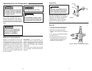
1. Remove the air compressor from the
carton.
2. Place the compressor on a secure,
stationary work surface and look it
over carefully.
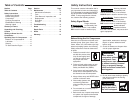
Unpacking and Checking Contents
Do not operate unit if damaged
during shipping, handling or
use. Damage may result in
bursting and cause injury or
property damage.
!
WARNING
For your own safety, never
operate unit until all assembly
steps are complete and until
you have read and understood
the entire operator’s manual.
!
WARNING
To reduce the risk of injury, if
any parts are missing, do not
attempt to assemble the air
compressor until the missing
parts are obtained and installed
correctly.
!
WARNING
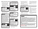
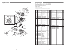
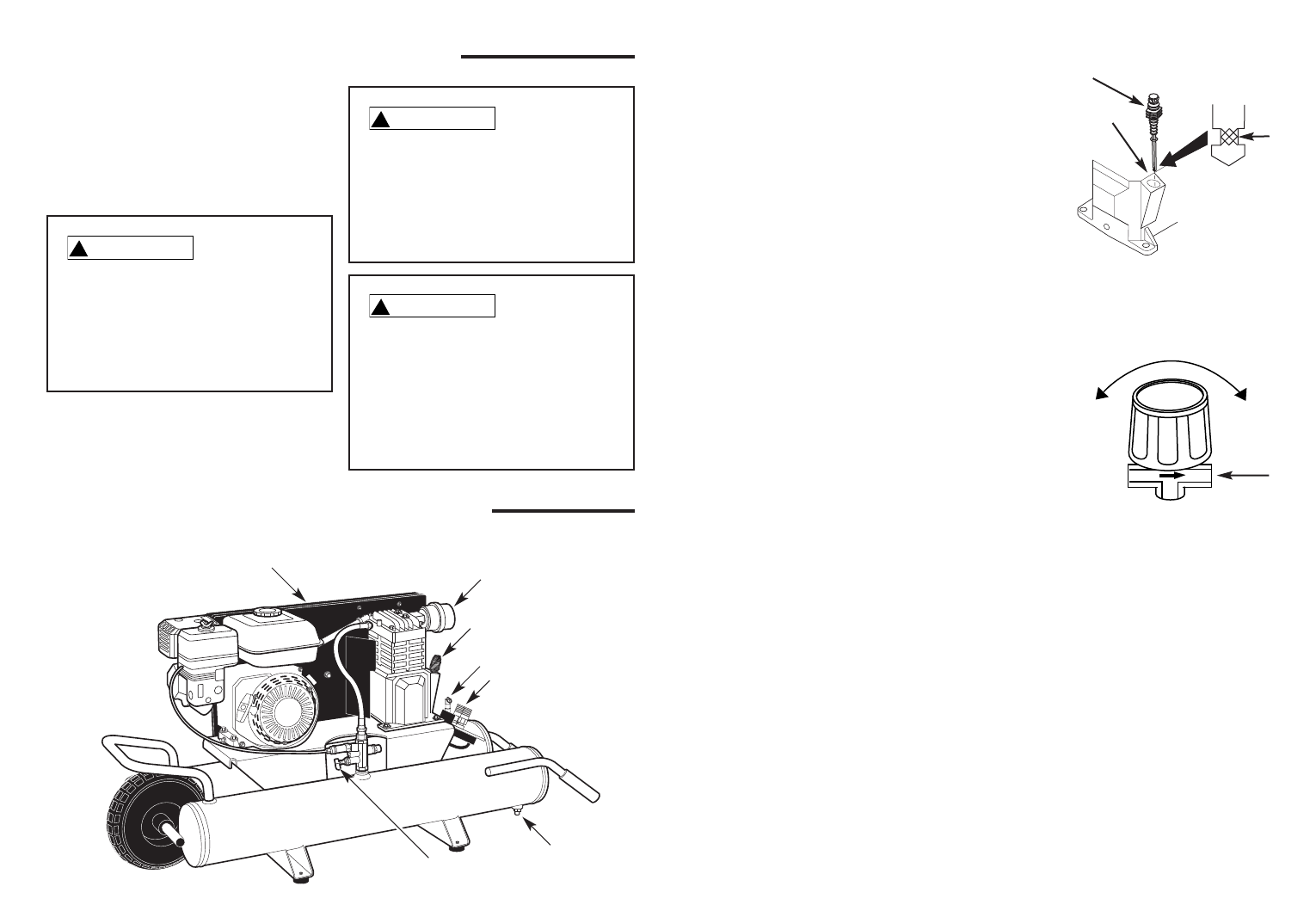
Figure 2
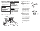
Getting to Know Your Air Compressor
1 Filter
2 Dipstick
3 Safety Valve
4 Regulator
5 Tank
Drain
6 Unloader
7 Beltguard
1. Air Filter.
The air filter keeps dirt and
debris from entering the compressor
pump.
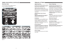
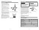
2. Dipstick. The dipstick measures the
oil level in the compressor pump (See
Figure 3).
3. ASME Safety Valve. This valve auto-
matically releases air if the tank pres-
sure exceeds the preset maximum.
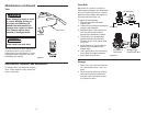
4. Regulator Knob. This knob controls
air pressure to an air operated tool or
paint spray gun. Turning the knob
clockwise increases air pressure at
the outlet. Turning counterclockwise
will lower air pressure at the outlet.
Fully counterclockwise will shut off
the flow of air completely (See Figure
4).
5. Tank Drain Valve. The tank drain
valve allows moisture to be removed
from the tank. Note that each tank
has its own tank drain valve.
6. Unloader. The unloader controls the
engine rpm. When loaded, the engine
will run at maximum operating speed
and air will enter the tank. When
unloaded, the engine will slow to an
idle and air will vent to atmosphere.
7. Belt Guard. The belt guard encloses
the pulleys and drive belt. It protects
the user from moving parts and
directs cooling air to the compressor
pump
Dipstick
Add Oil
Fill
Line
Max
Low
Figure 3
Close
Open
Attach
Hose
Figure 4