


11
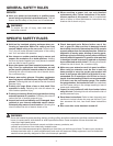
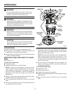
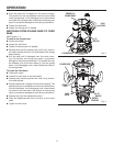
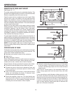
Fig. 4
SPINDLE
LOCK
LOCK
LEVER
MOTOR
HOUSING
TO
UNLOCK
PLUNGE BASE
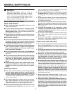
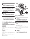
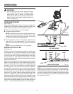
Fig. 3
LOCK
LEVER
TO
UNLOCK
GROOVE IN
PLUNGE BASE
LOCKING ARM
Push the base until it lodges into the motor housing.
The spindle lock can be released once the motor slides
inside plunge base. It will disengage once it has cleared
the inside of the plunge base. Use caution as forcing may
result in permanent damage to the locking mechanism.
Tighten the lock lever.
Loosen the locking arm if needed.
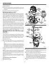
SWITCHING FROM PLUNGE BASE TO FIXED
BASE
See Figures 3 - 4.
To remove the plunge base:
Unplug the router.
Loosen the lock lever.
Tighten the locking arm for stability.
Depress and hold the spindle lock (until it fully locks in
the collet spindle) so that it will slide behind the plunge
base housing.
Pull the base until it dislodges from the motor hous-
ing. Use caution, as forcing may result in permanent
damage to the locking mechanism. The spindle lock can
be released once the motor slides up into the plunge
base. It will disengage once it has cleared the inside of
the plunge base.
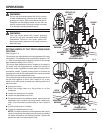
To install the fixed base:
Unplug the router.
Loosen the lock lever on the fixed base.
Depress and hold the spindle lock until it fully locks in
the collet spindle.
Push the base until it lodges into the motor housing. The
spindle lock can be released once the motor slides down
into the fixed base. It will disengage once it has cleared
the inside of the fixed base. Use caution as forcing may
result in permanent damage to the locking mechanism.
Depress and hold the adjustment button.
Place the adjustment bar tab in the slot on the motor
base.
Tighten the lock lever.
OPERATION