


21
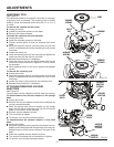
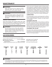
PIN
SPINDLE
LOCK
CONE
SUBBASE
COLLET
NUT
SUBBASE
SCREWS
SUBBASE
SCREWS
Fig. 23
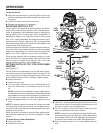
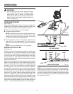
ADJUSTMENTS
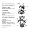
CENTERING TOOL
See Figure 23.
If the subbase needs to be replaced, removed, or changed,
a centering tool is provided. The centering tool is double
sided to center the subbase when using the 1/2 in. or 1/4
in. collet.
To remove the subbase on the router:
Unplug the router.
� Loosen the subbase screws on the base.
Remove the router subbase.
To install the centering tool and subbase:
Unplug the router.
� Insert the subbase screws on the base.
�Tighten screws lightly so that the subbase can move
freely.
Using the supplied wrench, hold the collet nut with one
wrench or depress and hold the spindle lock until it locks
into place.
Loosen the collet nut.
� Insert the centering tool pin into the collet and tighten the
collet securely with the wrench provided.
Release the spindle lock if necessary.
� Place the cone on the pin and lightly press down on the
cone until it stops as shown in figure 23. This will center
the subbase.
� While pressing down on the cone, tighten the subbase
screws.
To remove the centering tool:
Unplug the router.
Using the supplied wrench, hold the collet nut with one
wrench or depress and hold the spindle lock until it locks
into place.
Loosen the collet nut and remove the centering tool.
Release the spindle lock if necessary.
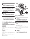
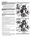
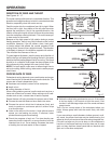
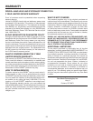
ATTACHING/REMOVING VACUUM
ADAPTORS
See Figure 24.
The provided vacuum adaptors provide dust free routing.
To attach/remove the vacuum adaptor to the plunge
base:
Unplug the router.
Remove the vacuum adaptor screws on the subbase by
turning counterclockwise.
Place the plunge base vacuum adaptor on the plunge
base with the screw openings lined up with the screw
holes on the bottom of the subbase.
Reinsert vacuum adaptor screws.
Turn clockwise to tighten.
To remove, turn screws counterclockwise.
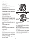
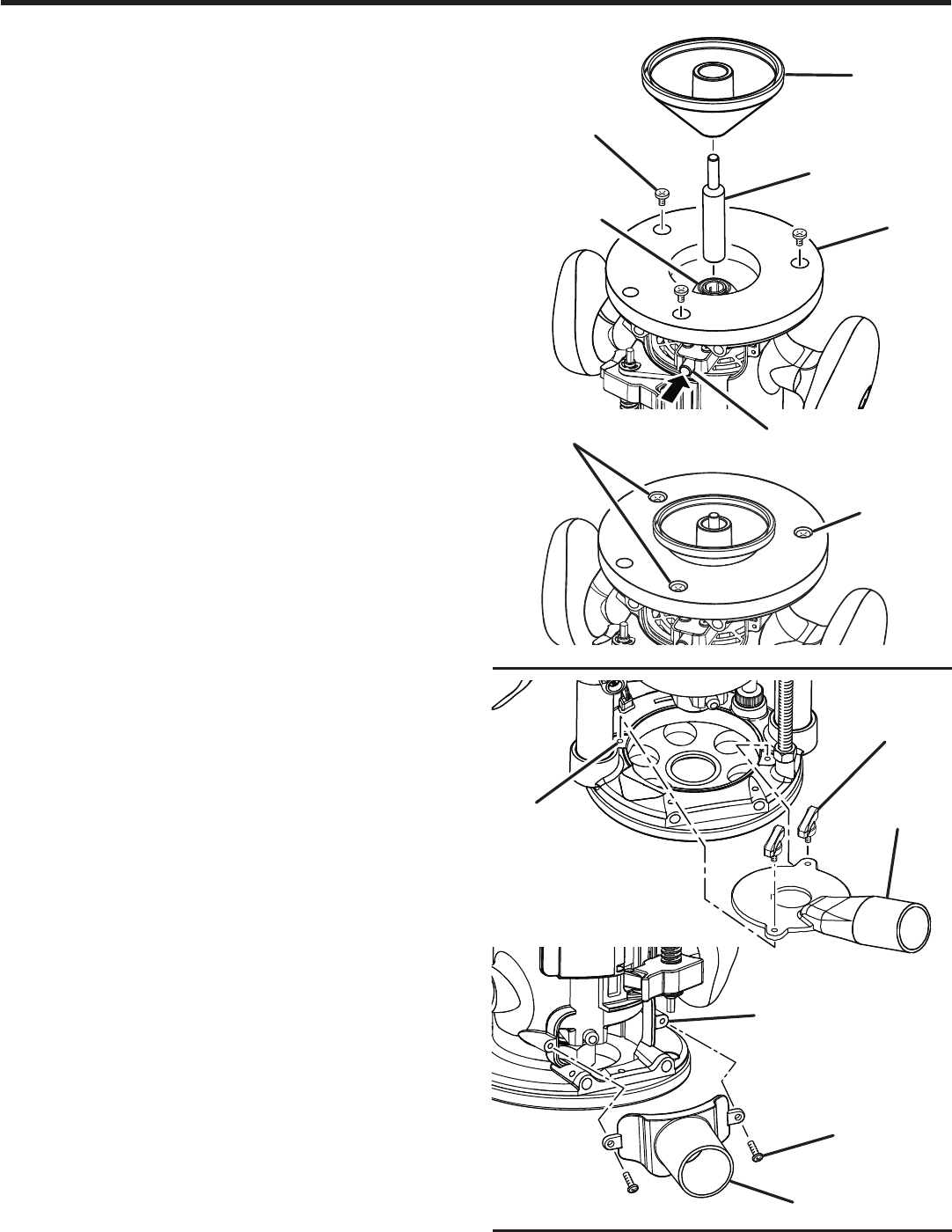
To attach/remove the vacuum adaptor to the fixed
base:
Unplug the router.
Using the supplied screws, place the fixed base vacuum
adaptor on the fixed base with the openings in the vacuum
adaptor lined up with the screw holes on the back of the
base.
Insert the supplied vacuum adaptor screws.
Turn screws clockwise with a screwdriver to tighten.
To remove, turn screws counterclockwise.
SUBBASE
SCREWS
Fig. 24
VACUUM
ADAPTOR
SCREWS
VACUUM
ADAPTOR
SCREW
HOLES
VACUUM
ADAPTOR
SCREW
HOLES
VACUUM
ADAPTOR
SCREWS