


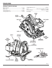
16
56
0
56
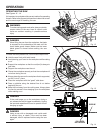
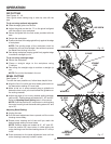
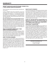
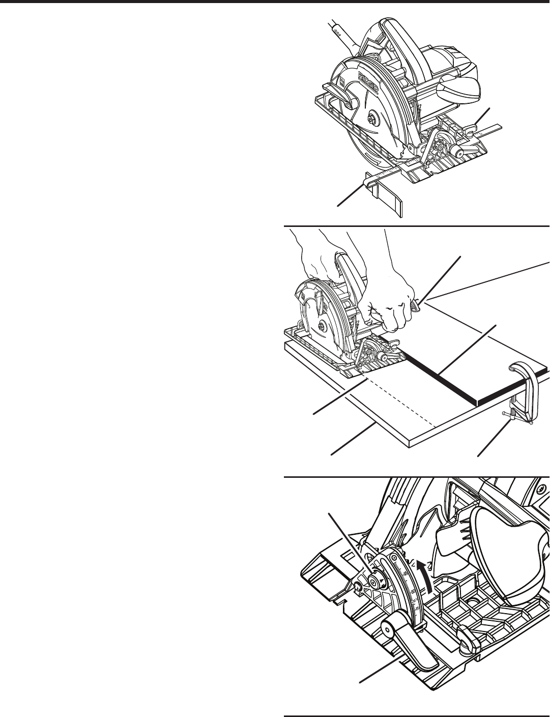
RIP CUTTING
See Figures 15 - 16.
Use a guide when making long or wide rip cuts with the
saw.
To rip cut using optional edge guide:
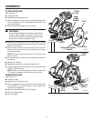
Slide the edge guide into the slot.
Adjust the guide so that the "0" on the guide is aligned
with the edge of your workpiece.
Secure the guide with the lock screw provided with the
saw.
Secure the workpiece.
Position the face of the edge guide firmly against the edge
of workpiece.
NOTE: The guiding edge of the workpiece must be
straight for your cut to be straight. Use caution to prevent
the blade from binding in the cut.
Saw along workpiece keeping guide firmly against edge
to achieve a straight rip cut.
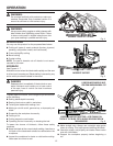
To rip cut using a straight edge:
Secure the workpiece.
Clamp a straight edge to the workpiece using
C-clamps.
Saw along the straight edge to achieve a straight rip
cut.
NOTE: Do not bind the blade in the cut.
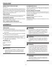
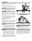
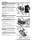
BEVEL CUTTING
See Figures 17 - 19.
To make the best possible cut, follow these helpful hints:
Align the line of cut with the inner blade guide notch on
the base when making 45° bevel cuts.
Make a trial cut in scrap material along a guideline to
determine how much you should offset the guideline on
the cutting material.
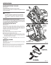
Adjust the angle of cut to any desired setting between
zero and 56°. Positive stops are located at 0°, 45° and 56°.
Refer to Adjusting Bevel Setting later in this manual.
NOTE: Push the positive 56° stop button in while raising
the motor housing to set the bevel setting above 45° and
up to 56°.
Adjusting Bevel Setting:
Unplug the saw.
Pull the bevel adjustment lever upward until the motor
housing moves freely.
Rotate motor housing end of saw until you reach the
desired angle setting on bevel scale.
NOTE: Positive stops are located at 0°, 45° and 56°.
Push the positive 56° stop button in while raising the
motor housing to set the bevel setting above 45° and up
to 56°.
Push downward on the bevel adjustment lever until the
motor housing is securely locked in place.
OPERATION
Fig. 16
Fig. 15
EDGE GUIDE
STRAIGHT
EDGE
C-CLAMP
wORKPIECE
GUIDELINE
BEvEL
ADJUSTMENT
LEvER
56° BEvEL
BUTTON
Fig. 17
C-CLAMP
LOCK SCREw