


13
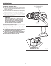
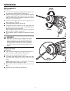
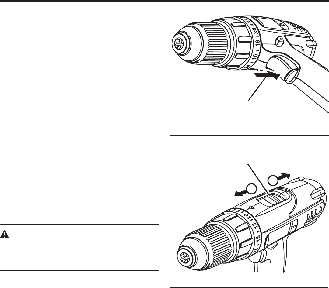
SWITCH
See Figure 6.
To turn your drill ON, depress the switch trigger. To turn it
OFF, release the switch trigger.
VARIABLE SPEED
See Figure 6.
This tool has a variable speed switch that delivers higher
speed and torque with increased trigger pressure. Speed is
controlled by the amount of switch trigger depression.
This drill has an electric brake. When the trigger switch
is released, the chuck stops turning. When the brake is
functioning properly, sparks will be visible through the vent
slots on the housing. This is normal and is the action of
the brake.
Note: You might hear a whistling or ringing noise from the
switch during use. Do not be concerned, this is a normal
part of the switch function.
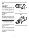
REVERSIBLE
See Figure 4.
This tool has the feature of being reversible. The direction of
rotation is controlled by a selector located above the switch
trigger. With the drill held in normal operating position, the
direction of rotation selector should be positioned to the left
of the switch for drilling. The drilling direction is reversed
when the selector is to the right of the switch. When the
selector is in center position, the switch trigger is locked.
CAUTION:
To prevent gear damage, always allow chuck to
come to a complete stop before changing the
direction of rotation or the two speed gear train
(hi-lo).
To stop, release switch trigger and allow the chuck to come
to a complete stop.
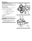
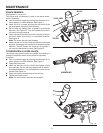
TWO-SPEED GEAR TRAIN
See Figure 7.
Your drill has a two-speed gear train designed for drilling or
driving at LO (1) or HI (2) speeds. A slide switch is located on
top of your drill to select either LO (1) or HI (2) speed. When
using drill in the LO (1) speed range, speed will decrease
and unit will have more power and torque. When using drill
in the HI (2) speed range, speed will increase and unit will
have less power and torque. Use LO (1) speed for high power
and torque applications and HI (2) speed for fast drilling or
driving applications.
HI
SPEED
LO
SPEED
TWO SPEED
GEAR TRAIN (HI-LO)
1
Fig. 7
OPERATION
Fig. 6
VARIABLE SPEED
SWITCH TRIGGER
2