


14
ASSEMBLY
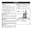
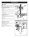
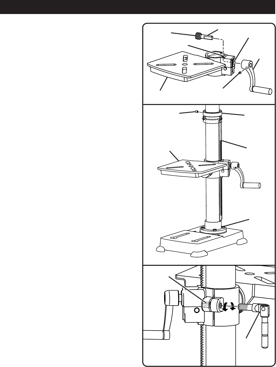
INSTALLING TABLE ASSEMBLY
See Figures 6 - 8.
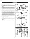
Loosen the set screw in the column collar. Remove the
column collar and gear rack from the column and set
aside.
Locate the worm gear and feed the D-shaft through the
hole in the table assembly.
Install table adjustment handle over the end of the D-shaft
so that the flat side of the shaft aligns with the set screw.
Tighten the set screw using the hex key.
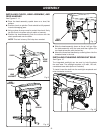
Feed the gear rack through the slot in the table assembly
so that the teeth are facing out and the longer smooth end
faces up. The worm gear should engage the gear rack.
Using both hands, slide the entire table assembly and gear
rack onto the column until the bottom of the gear rack is
positioned in the base collar and against the column.
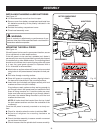
Slide the column collar, bevel-side down, over the column
until the beveled side engages the beveled end of the
gear rack. Tighten the set screw in the collar using the
hex key. Do not overtighten.
NOTE: You should be able to move the table from side
to side.
Locate the table lock handle. Insert it into the threaded
hole at the rear of the table assembly and tighten by
hand.
worm
GEar
sET scrEw
TabLE
adjusTmEnT
handLE
basE
coLLar
Fig. 6
Fig. 7
TabLE
assEmbLy
hoLE
d-shafT
GEar
rack
TabLE
assEmbLy
sLoT
sET scrEw
ThrEadEd
hoLE
coLumn
coLLar
TabLE
Lock
handLE
Fig. 8