


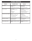

13
1
2
D
r
l
l
i
P
r
e
s
s
O
N
R
E
M
O
V
E
T
O
L
O
C
K
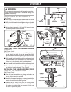
ADJUSTMENTS
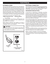
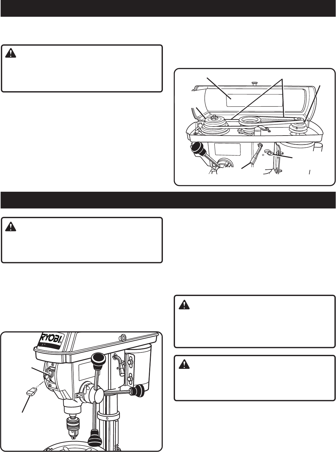
Fig. 14
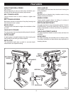
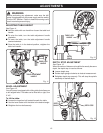
BELT TENSION
LEVER
CHANGING SPEEDS
See Figure 14.
WARNING:
Before performing any adjustment, make sure the drill
press is unplugged from the power supply and the switch
is in the OFF position. Failure to heed this warning could
result in serious personal injury.
The spindle speed is determined by the location of the belts
on the pulleys inside the head assembly. The speed chart
located on the cover inside the head assembly shows the
recommended speed and pulley configuration for each drilling
operation. To change the pulley configuration, refer to figure
14 and proceed as follows:
■ Loosen the two belt tension screws located on each side of
the head assembly.
■ Push the belt tension lever to release belt tension and to
loosen the belts.
OPERATION
WARNING:
Before attempting to use your drill press familiarize
yourself with all operating features and safety
requirements.
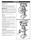
LOCKING THE SWITCH
See Figure 15.
■ Place the switch in the OFF position.
■ Wait until the drill press has come to a full and complete
stop.
■ Remove the switch key from the switch assembly. Store
key in safe place.
SWITCH KEY
SWITCH
Fig. 15
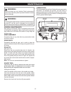
SELF-EJECTING CHUCK KEY
The self-ejecting chuck key ensures that the chuck key is
removed from the chuck BEFORE the drill press is turned
on.
In order to loosen or tighten the chuck using the chuck key,
push the key into the chuck hole. Rotate the key clockwise
to tighten the chuck, counterclockwise to loosen the chuck.
When you are finished with the chuck key, always replace it
in the chuck key storage located on the head assembly.
WARNING:
Use only the self-ejecting chuck key provided. Always
remove chuck key and store in the on-board chuck key
storage. Failure to heed this warning could result in
serious personal injury.
WARNING:
Always remember to remove the chuck key from the table
surface before turning on the drill press. Failure to heed
this warning could result in serious personal injury.
TABLE ROTATION
When drilling large objects it may be necessary to swing the
table out of the way. Simply loosen the table lock lever, rotate
the table, and retighten table lock lever.
Note: When using the base as a work surface, the workpiece
must be clamped securely to the base.
BELT TENSION
SCREWS
MOTOR
PULLEY
SPEED CHART
BELTS
SPINDLE
PULLEY
■ Open the head assembly cover and reposition the belt
according to the speed chart. Close the cover.
■ Push the belt tension lever firmly back into position
assuring drive belt is tight. While holding tension on the
motor, retighten the two belt tension knobs securely.