9
FEATURES
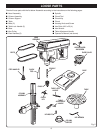
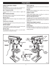
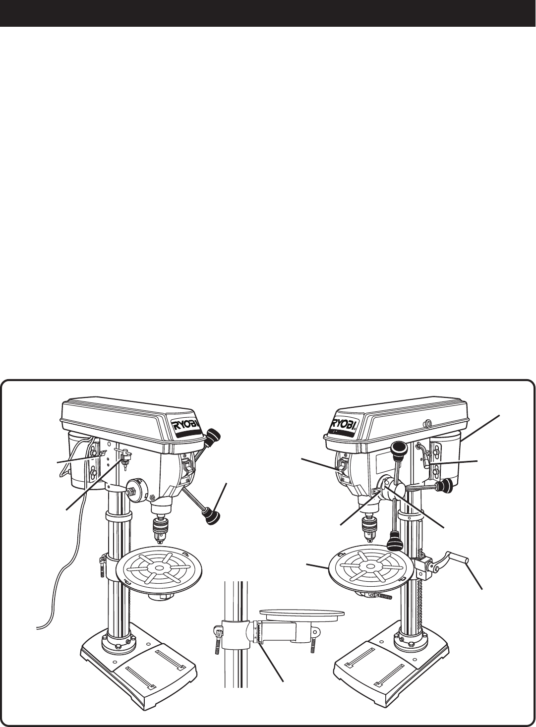
Fig. 3
KNOW YOUR DRILL PRESS
See Figure 3.
Before attempting to use your drill press, familiarize your-
self with all the operating and safety requirements.
BELT TENSION LEVER
The belt tension lever is used to release or tighten belt
tension.
BELT TENSION SCREWS
Belt tension screws on each side of the pulley housing lock
the belt tension lever in place.
BEVEL SCALE
The bevel scale indicates the degree the worktable is tilted
up to 45°.
CHUCK KEY STORAGE
For easy access, the chuck key should be placed in the built-
in chuck key storage.
DEPTH GAUGE
A depth gauge is located between the pulley housing and
feed handles to aid drilling at desired depths.
DEPTH STOP
The adjustable depth stop is used for accurate depth
measurement and repetitive drilling.
FEED HANDLES
Feed handles raise and lower the chuck and bit during the
drilling operation.
MOTOR
Equipped with an industrial duty, induction motor for long
lasting, smooth performance.
SPINDLE SPEED
Twelve spindle speeds allows for drilling of a variety of
materials from wood to plastic to metal.
SWITCH AND SWITCH KEY
Your drill press has an easy access power switch. To lock in
the OFF position, remove the switch key. Place the key in a
location inaccessible to children and others not qualified to
use the tool.
TABLE ADJUSTMENT HANDLE
The table adjustment handle is used to raise and lower the
worktable.
WORKTABLE
For added versatility, the worktable can be rotated or tilted.
The slotted worktable and base allows easy application of
clamping devices.
1
2
D
r
l
l
i
P
r
e
s
s
O
N
1
/
2
”
D
r
i
l
l
P
r
e
s
s
BELT TENSION
LEVER
BELT TENSION
SCREWS
BEVEL SCALE
CHUCK KEY
STORAGE
DEPTH
GAUGE
DEPTH
STOP
FEED HANDLES
MOTOR
SWITCH
AND
SWITCH KEY
TABLE
ADJUSTMENT
HANDLE
WORKTABLE
0
0
10
20
30
40
10
20
30
40


