


20 21
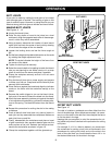
MAINTENANCE
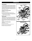
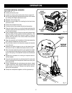
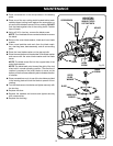
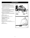
Fig. 23
NON-CUTTING
TOOTH BEHIND
CARBIDE-TIPPED
CUTTING TOOTH
SCREWDRIVER
BLADE
HEX KEY
BLADE
SCREW
n Place a screwdriver in the hole provided in the bearing
plate.
n Place one of the non-cutting teeth located behind each
carbide-tipped cutting tooth against the screwdriver or
pin and lock the blade to prevent it from rotating. DO NOT
lock the blade against one of the cutting teeth. Carbide
tips will break.
n Using a 3/16 in. hex key, remove the blade screw.
NOTE: Turn the blade screw counterclockwise to remove
the blade.
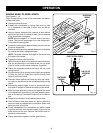
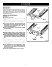
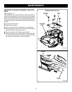
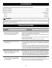
n Remove the outer blade washer, blade and inner blade
washer.
n Clean wood particles and resin from the blade wash-
ers, dust bag area, base assembly, and all surrounding
parts.
n Place the inner blade washer on the gear spindle.
n Place the new blade onto the shoulder of the blade washer
and secure with the outer blade washer and the blade
screw.
NOTE: The blade screw fits into the cupped side of the
outer blade washer.
NOTE: The blade teeth point toward the right of the tool
when held in normal operating position. The direction of
rotation is marked on the joiner blade. An arrow on the
bottom of the front base assembly also indicates direction
of rotation.
n Place a screwdriver or pin in one of the two holes provided
in the bearing plate and lock the blade to prevent it from
rotating.
n Turn the blade screw clockwise and tighten securely with
the hex key.
n Replace the shoe.
n Replace the washers and screws and tighten securely
with a screwdriver.
n Replace the dust bag.
BLADE
SCREW
BLADE
INNER BLADE
WASHER
OUTER
BLADE
WASHER
GEAR
SPINDLE
Fig. 24