


11
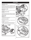
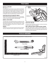
SWITCH TRIGGER
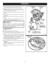
See Figure 6.
To prevent unauthorized use of your compound miter saw,
remove battery pack and lock the switch in the off position.
To lock the switch, install a padlock through the hole in the
switch trigger. A lock with a shackle up to 9/32 in. diameter
may be used. When the lock is installed and locked, the switch
is inoperable. Store the padlock key in another location.
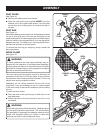
POSITIVE STOPS ON MITER TABLE
Positive stops have been provided at 0°, 22-1/2°, 30°, and 45°.
The 22-1/2°, 30° and 45° positive stops have been provided
on both the left and right side of the miter table.
BEVEL LOCK KNOB
The bevel lock knob securely locks your compound miter
saw at desired bevel angles. Positive stop adjustment screws
have been provided on each side of the saw arm. These
positive stop adjustment screws are for making fine adjust-
ments at 0° and 45°.
FENCE
The fence on your compound miter saw has been provided to
hold your workpiece securely against when making cuts.
PADLOCK
SWITCH
TRIGGER
FEATURES
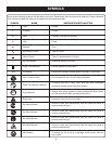
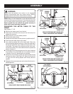
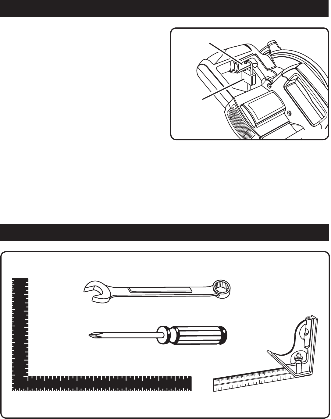
The following tools are needed for making adjustments or installing the blade:
TOOLS NEEDED
Fig. 7
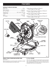
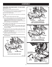
ELECTRIC BRAKE
An electric brake has been provided to quickly stop blade
rotation after the switch is released.
SELF-RETRACTING LOWER BLADE GUARD
The lower blade guard is made of shock-resistant, see-
through plastic that provides protection from each side of
the blade. It retracts over the upper blade guard as the saw
is lowered into the workpiece.
FRAMING SQUARE
PHILLIPS SCREWDRIVER
COMBINATION
SQUARE
Fig. 6
COMBINATION WRENCH (2)
17 mm ,10 mm