


14
ASSEMBLY
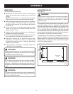
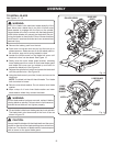
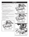
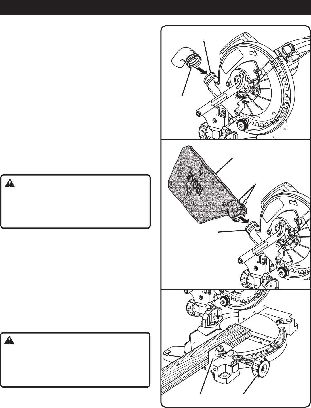
DUST GUIDE
See Figure 10.
n Remove the battery pack from the tool.
n Place the dust guide (end marked INSERT) over the
exhaust port in the upper blade guard. Turn the guide
so the open end is facing down or towards the rear of
the saw.
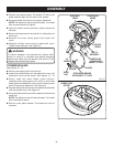
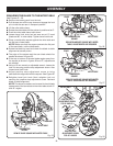
DUST BAG
See Figure 11.
Remove the battery pack from the tool. A dust bag is provided
for use on this miter saw. It fits over the dust guide on the
upper blade guard. To install, squeeze the two metal clips to
open the mouth of the bag and slide it on to the dust guide.
Release the clips. The metal ring in the bag should lock in
between the grooves on the dust guide.
To remove the dust bag for emptying, simply reverse the
above procedure.
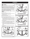
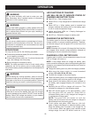
WORK CLAMP
See Figure 12.
WARNING:
In some operations, the work clamp assembly may in-
terfere with the operation of the blade guard assembly.
Always make sure there is no interference with the blade
guard prior to beginning any cutting operation to reduce
the risk of serious personal injury.
The work clamp provides greater control by clamping the
workpiece to the fence or the saw table. It also prevents
the workpiece from creeping toward the blade. This is very
helpful when cutting compound miters.
Depending on the cutting operation and the size of the
workpiece, it may be necessary to use a C-clamp instead
of the work clamp to secure the workpiece prior to making
the cut.
To install the work clamp:
n Place the shaft of the work clamp in either hole on the
saw table base.
n Rotate the knob on the work clamp to move it in or out
as needed.
WARNING:
When using any clamp with a stop block, install the clamp
on the same side as the stop block. This will eliminate
the possibility of trapping the workpiece, resulting in the
blade and workpiece kicking up. Failure to heed this
warning can result in serious personal injury.
4
5
3 0
15
15
30
4
5
22.5
31.62
22. 5
31.62
R
O
T
A
T
I
O
N
EXHAUST
PORT
DUST
GUIDE
Fig. 10
4
5
3 0
15
15
30
4
5
22.5
31.62
22. 5
31.62
R
O
T
A
T
I
O
N
EXHAUST
PORT
DUST
BAG
METAL
CLIPS
Fig. 11
4
5
3 0
15
15
30
4
5
22.5
31.62
22. 5
31.62
R
O
T
A
T
I
O
N
Fig. 12
WORK CLAMP
KNOB