


Page 12
15˚
30˚
45˚
0˚
45˚
30˚
15˚
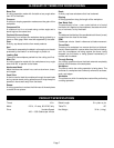
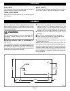
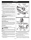
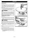
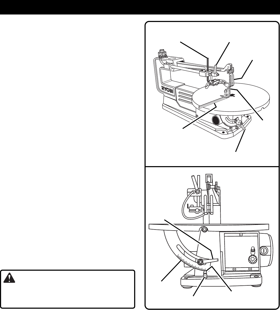
SQUARING TABLE TO THE BLADE
See Figures 8 and 9.
■ Loosen the hold down foot lock lever and move hold down
rod all the way up. Tighten lever.
■ Loosen the table lock lever and move the table until it is
approximately perpendicular, or at right angle to the
blade.
■ Place a small square on the table next to the blade to
check if the table is 90 degrees to the blade. If adjustment
is needed, raise or lower the table until table is 90 degrees
to the blade and securely tighten the table lock lever.
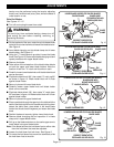
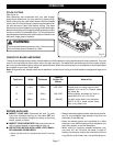
■ Loosen the screw holding the scale indicator, move
indicator to the 0 degree mark and securely tighten screw.
Remember, the bevel scale is a convenient guide but
should not be relied upon for precision. Make practice
cuts on scrap material to determine if your angle settings
are correct.
■ Adjust the hold down foot to desired position and securely
tighten the hold down foot lock lever.
SETTING THE TABLE FOR HORIZONTAL OR
BEVEL CUTTING
See Figure 9.
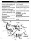
A bevel scale is provided under the work table as a conve-
nient guide for setting the approximate table angle for bevel
cutting. When greater precision is required, make practice
cuts on scrap material and adjust the table as necessary for
your requirements.
INSTALLING BLADES
Scroll saw blades wear out quickly and must be replaced
frequently for best cutting results. Expect to break some
blades while you learn to use and adjust your saw. Blades
generally stay sharp for 1/2 hour to 2 hours of cutting,
depending on type of material and speed of operation.
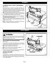
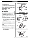
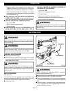
Pin End Blades
See Figures 10 and 11.
■ Turn off and unplug the saw from outlet.
WARNING:
To avoid injury from accidental starting, always turn off
and unplug the saw before installing, removing or replacing
the blade.
■ On the top back of the saw, rotate the quick release knob
to the left or counterclockwise to loosen blade tension.
See Figure 4.
■ Place blade through the opening with the teeth of the
blade to the front of the saw and pointing down toward the
table. Engage the pin into the "V" notch of the lower blade
holder.
See Figure 10.
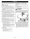
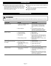
■ Pull up on the blade and push down on the saw arm to
engage the upper pin in the "V" notch of the upper blade
holder.
See Figure 11.
ADJUSTMENTS
Fig. 9
TABLE LOCK
LEVER
BEVEL
SCALE
SCALE
INDICATOR
SCREW
Fig. 8
HOLD DOWN FOOT/
BLADE GUARD
HOLD DOWN FOOT
LOCK LEVER
SMALL
COMBINATION
SQUARE
SAW
BLADE
HOLD
DOWN ROD
TABLE LOCK
LEVER
Note: If the blade touches the hold down foot on either side
then the hold down foot must be adjusted.
■ Loosen the hold down foot lock lever.
See Figure 8.
■ To center the hold down foot around the saw blade, slide
the hold down foot to the side.
■ Tighten the hold down foot lock lever.
■ To tension the blade, rotate the quick release knob (outer,
larger knob) 1/4 turn to the right or clockwise to apply
tension to the blade. Fine adjustments of the blade