


Page 15
ADJUSTMENTS
WARNING:
Failure to unplug your saw could result in accidental
starting causing possible serious personal injury.
■ Push down on the saw arm and pull out the lock pin to
release the saw arm.
■ Raise saw arm to its full raised position.
■ Loosen the miter lock handle approximately one-half
turn.
■ Depress the miter lock plate and rotate the miter table
until the pointer on the control arm is positioned at 0
°
.
■ Release the miter lock plate and securely tighten the
miter lock handle.
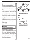
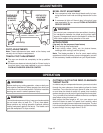
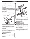
■ Lay a framing square flat on the miter table. Place one
leg of the square against the fence. Place the other leg
of the square beside the zero clearance throat plate in
the miter table. The edge of the square and the zero
clearance throat plate in the miter table should be paral-
lel as shown in figure 15.
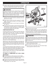
■ If the edge of the framing square and the zero clearance
throat plate in the miter table are not parallel as shown
in figures 14 and 15, adjustments are needed.
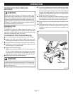
■ Using the blade wrench provided, loosen the socket
head screws securing the fence.
See Figure 16.
Adjust
the fence left or right until the framing square and zero
clearance throat plate are parallel.
■ Retighten the screws securely and recheck the fence-
to-table alignment.
SQUARING THE SAW BLADE TO THE FENCE
See Figures 16 - 20
■ Unplug your saw.
WARNING:
Failure to unplug your saw could result in accidental
starting causing possible serious personal injury.
■ Pull the saw arm all the way down and engage the lock
pin to hold the saw arm in transport position.
■ Loosen the miter lock handle approximately one-half
turn.
■ Depress the miter lock plate and rotate the miter table
until the pointer on the control arm is positioned at 0
°
.
■ Release the miter lock plate and securely tighten the
miter lock handle.
■ Lay a framing square flat on the miter table. Place one
leg of the square against the fence. Slide the other leg
of the square against the flat part of saw blade.
Note: Make sure that the square contacts the flat part of
the saw blade, not the blade teeth.
FRAMING
SQUARE
Fig. 14
VIEW OF MITER TABLE NOT SQUARE WITH
FENCE, ADJUSTMENTS ARE REQUIRED
MITER FENCE
ZERO CLEARANCE
THROAT PLATE
MITER TABLE
FRAMING
SQUARE
MITER
FENCE
Fig. 15
VIEW OF MITER TABLE NOT SQUARE WITH
FENCE, ADJUSTMENTS ARE REQUIRED
MITER TABLE
ZERO CLEARANCE
THROAT PLATE
Fig. 16
45
30
45
30
31.6
3
1
.6
5
1
1
5
22.5