10
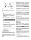
3. Place the Amp Probe around the starter cable.
4. Connect the external volts positive lead to the positive terminal
of the starter.
5. Connect the external volts negative lead to the starter ground.
6. Set the Volts Selector to External Volts ±199.9 volt range.
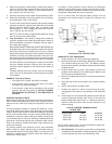
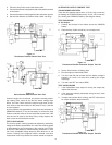
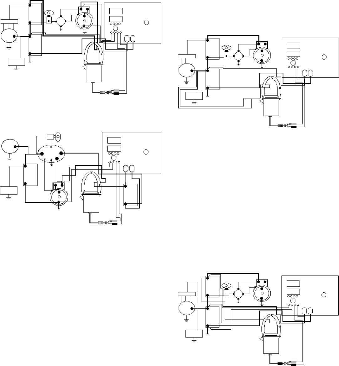
Figure 11
Transformer Rectifier Starter Draw Test
STARTER
CHASSIS
BATTERY
CRANKING
BATTERY
ALT
TR
+
+
-
+
-
12V LOADS
MAG
SW
S
+ 24V
+ 12V
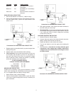
Figure 12
Series-Parallel Switch Starter Draw Test
STARTER
CHASSIS
BATTERY
SWITCH
ALT
+
+
-
12V LOADS
CRANKING
BATTERY
+
-
SERIES
PARALLEL
SWITCH
Crank the engine for 15 seconds, and note the cranking amper-
age reading. Also, watch to see that the starter voltage stays
above 19.2 volts. Never crank the engine longer than 30 sec-
onds. Wait at least two minutes for the starter to cool, if the test
is to be repeated.
In some medium-duty applications, where there are two banks of
CRANKING batteries, it may be necessary to connect the Amp
Probe around both wires at once to read total current draw. If the
wires are too far apart for the Amp Probe, simply measure the
draw in each wire and add the results.
TEST CONCLUSIONS
The circuit is good if cranking speed was satisfactory and battery
voltage at the starter stayed above 19.2 volts. Slow cranking speed
is often caused by poor connections in the cranking circuit. Refer
to the PST-1000 manual for troubleshooting information. In a 24
volt circuit, acceptable voltage drops are twice those for 12 volt
circuits. If testing of the magnetic switch, solenoid, and other
components reveal no problems, the starter should be replaced.
ALTERNATOR OUTPUT CURRENT TEST
TRANSFORMER RECTIFIER
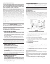
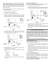
There are two separate output wires. A 12 volt, high current out-
put feeding the CHASSIS battery and a 24 volt, low current out-
put, feeding the CRANKING battery. (See diagram below).
TEST PROCEDURE
12 Volt Output
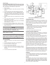
1. Connect the Analyzer’s load cables across the CHASSIS
battery.
2. Place the Amp Probe around the 12 volt output wire.
Figure 13
Transformer-Rectifier Alternator Output Test-12V
STARTER
CHASSIS
BATTERY
CRANKING
BATTERY
ALT
TR
+
+
-
+
-
12V LOADS
MAG
SW
S
+ 24V
+ 12V
3. Set the Volts Selector to Battery Volts.
4. Run the engine at about 2000 RPM.
5. Turn the Load ON and increase until the battery voltage is
between 12.5 and 13.5 volts while reading the output
amperage.
6. Turn the Load OFF and reduce RPM.
TEST CONCLUSIONS
1. If the Diode/Stator lamp stayed on during the output test,
replace the alternator.
2. If the amperage abruptly decreased during the test, check
for a loose belt.
3. If output was less than 90% of rating, see PST-1000 manual
for output resistance test procedures.
Figure 14
Transformer-Rectifier Alternator Output Test-24V
STARTER
CHASSIS
BATTERY
CRANKING
BATTERY
ALT
TR
+
+
-
+
-
12V LOADS
MAG
SW
S
+ 24V
+ 12V


