9
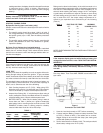
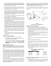
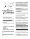
Figure 10
BLACK
SOLENOID
RELAY
BATTERY
CHASSIS
RED
+
+
-
A
B
DISCONNECT
REGULATOR
JUMPER
ALTERNATOR
OUT
FIELD
STEPS FOR EXTERNAL REGULATOR (TYPE) ALTERNA-
TOR
1. Make connections according to figure 10 above.
2. With ignition key OFF,
unplug regulator or disconnect field
wire.
3. Measure voltage at alternator field terminal. If at battery volts,
jumper the field terminal to the alternator case. If no volts,
jumper to the alternator output terminal. If there is no spark
when making this connection the field circuit is broken.
Continue to step 4.
STEPS FOR INTERNAL REGULATOR (TYPE) ALTERNATOR
1. Make connections according to figure 10 (above).
2. This test can only be done if the alternator has a terminal for
full fielding.
Be sure to have specific knowledge of the
alternator’s terminals. Grounding the wrong point can
damage some alternators or burn up jumpers. A 10 amp
(inline) fused jumper can help minimize accidental damage.
3. Apply, or prepare to apply the field excitation when the engine
is at idle. Get a helper if necessary.
Continued from step 3
4. Start the engine and slowly bring RPM to 2000. Keep battery
voltage between 12.5V and 13.5V by applying loading from
the analyzer.
Never let the voltage exceed 16 volts.
5. Remember the amps reading, and return to idle.
6. Shut off the engine, the battery load, and the alternator field.
7. Test Conclusion
a. If output was less than 90% of rating, go back to the
Output Resistance Test.
b. Otherwise if the output is okay, the problem must be in
the regulator or its wiring.
CAPABILITIES FOR 24V SYSTEM
The PST-1000 is capable of performing Battery Load tests, Starter
Draw tests, and Alternator Current Output tests on 24 volt electri-
cal circuit.
CAUTION
Working with batteries can be hazardous! Please read the
SAFETY PRECAUTIONS on the front page of the PST-1000
manual.
CIRCUIT ARRANGEMENTS
Most 24 volt circuits utilize combinations of 12 volts batteries to
provide 24 volts to the starter motor, controls and accessories. A
CHASSIS battery (or bank of batteries) is used for the engine’s
12 volt circuits, and a CRANKING battery (or bank of batteries)
is added to the circuit to provide 24 volts to the starter motor.
Occasionally you may encounter banks of six volt batteries, or
even a single 24 volt battery. Six volt batteries may be Load tested
individually or in pairs, if wired in series. NEVER attempt to Load
test a 24 volt battery with the PST-1000.
The two most common charging/starting arrangements are the
TRANSFORMER-RECTIFIER, used on most newer engines, and
the SERIES-PARALLEL switch.
Always refer to the engine manufacturer’s instructions prior to
conducting any tests, as some engines may have components
and circuit arrangements that are not included in these examples.
TRANSFORMER RECTIFIER
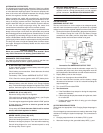
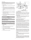
In a TRANSFORMER-RECTIFIER circuit, the CRANKING bat-
tery is always wired in series with the CHASSIS battery. The
TRANSFORMER-RECTIFIER alternator provides two separate
voltage outputs. A high current 12 volt output charges the CHAS-
SIS battery, and a low current 24 volt output charges the CRANK-
ING battery. The TRANSFORMER-RECTIFIER regulates the
charging voltage to both batteries automatically.
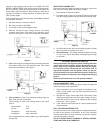
SERIES PARALLEL SWITCH
While charging, the CHASSIS battery and CRANKING battery
are switched in parallel. During cranking, the SERIES-PARAL-
LEL switch connects the CRANKING battery in series with the
CHASSIS battery, providing 24 volts to the starter motor.
The following procedures and diagrams apply to circuits with a
negative ground, a CHASSIS battery, a CRANKING battery, and
either a TRANSFORMER-RECTIFIER alternator or a SERIES-
PARALLEL switch.
BATTERY LOAD TEST
Batteries wired in series may be Load tested without disconnect-
ing cables. Those wired in parallel MUST be disconnected prior
to Load testing. Failure to do so will result in loading more than
one battery at a time and will yield inaccurate results. Perform
Load tests described earlier in the PST-1000 manual.
CAUTION
Always be sure that the Load is OFF before connecting the
analyzer’s Load cables to a battery.
To prevent damage to the SERIES-PARALLEL switch by high
current flow, batteries must be disconnected from the cir-
cuit prior to Load testing.
STARTER DRAW TEST
This test measures the amount of current drawn by the starter
motor during cranking. The procedures apply to both TRANS-
FORMER-RECTIFIER and SERIES-PARALLEL circuits. To pre-
vent the engine from starting, disable the ignition or fuel supply,
as recommended by the engine’s manufacturer.
TEST PROCEDURES
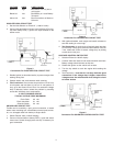
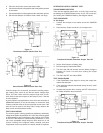
1. Connect the analyzer’s Load cables across any 12 volt
battery.
2. Make sure all lights and accessories are off and vehicle doors
are closed


