


6
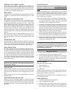
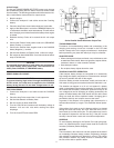
Figure 3
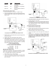
Connections For INSULATED-POS CIRCUIT TEST
BLACK
STARTER
SOLENOID RELAY
BATTERY
CHASSIS
POS
+
+
-
1. Disable ignition (as described earlier) to prevent engine from
starting during test.
2. Operate starter and read voltmeter while cranking.
3. Test Conclusion: Good circuits drop less than 0.4 volt on a
6 volt system and less than 0.5 volt on 12 volt systems. If
okay, go to the Ground Circuit Test. If an excessive voltage
drop is detected, further isolate the problem by retesting
across the individual circuit components.
12 VOLT CRANKING CIRCUIT
TYPICAL VOLTAGE DROP MAXIMUMS
Each Cable 0.2 volt
Each connection 0.1 volt
Solenoid Switch 0.3 volt
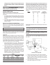
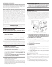
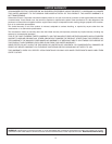
GROUND-NEG CIRCUIT TEST
Trouble can be caused by a poor ground connection, a loosed
starter motor mounting bolt, a bad battery terminal post connec-
tor, or a damaged cable from battery to engine block.
1. Select External Volts (±199.9V display)
2. Connect Volt test leads to battery NEG (-) post and starter
motor case. Scratch through paint with clip if necessary for
good connection.
Figure 4
Connection For GROUND-NEG CIRCUIT TEST
BATTERY
CHASSIS
BLACK
STARTER
RED
+
+
-
NEG
3. With ignition disabled, crank engine and watch voltmeter to
see that reading is not too high.
4. Test Conclusion: A good circuit will typically have less than
0.2 volt drop. If okay, go to Solenoid Control Switch Test, but
if not, isolate the cause of excess voltage drop by testing
across each circuit part.
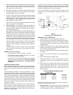
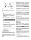
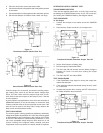
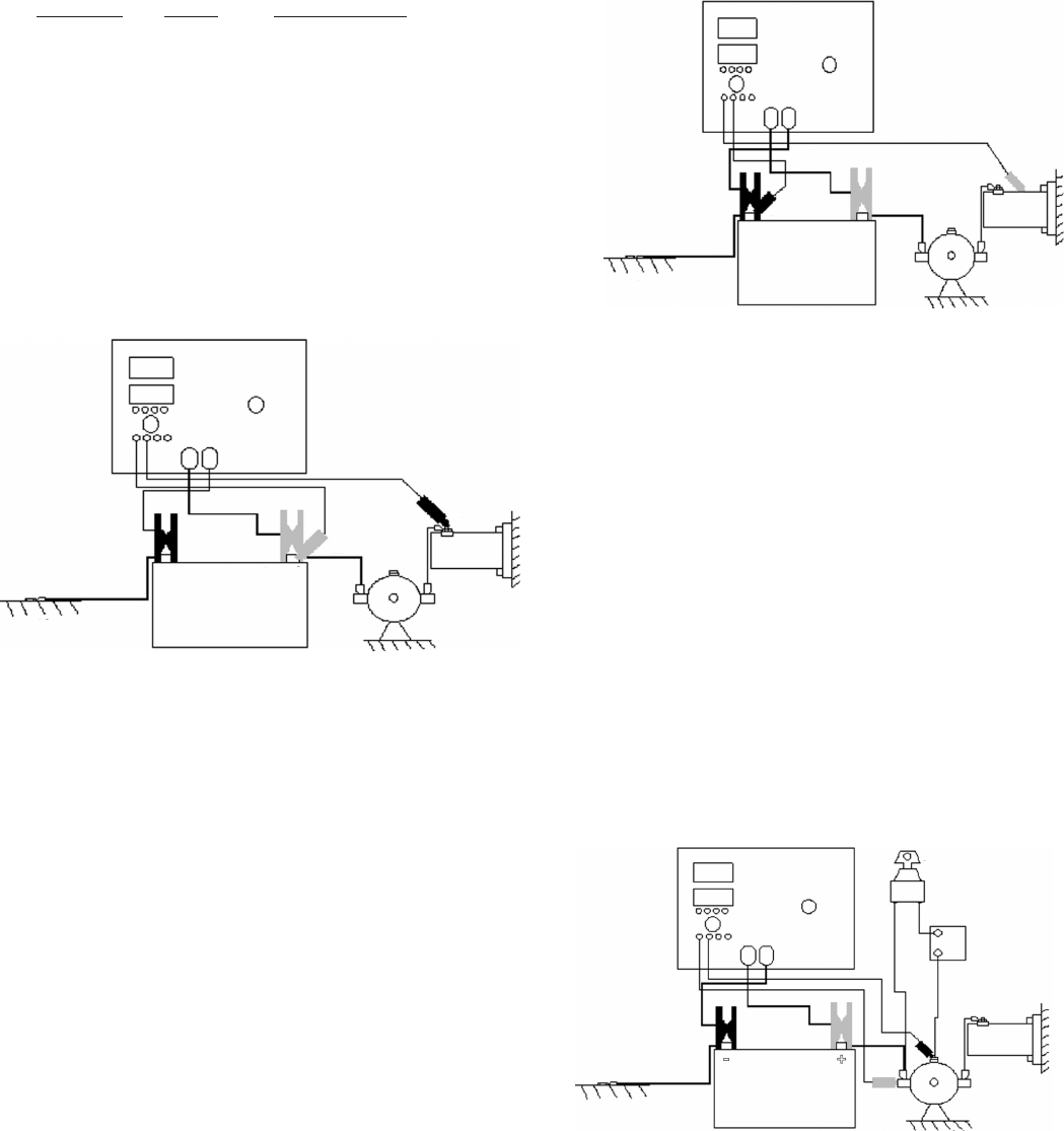
SOLENOID CONTROL SWITCH TEST
1. Selection External ±199.9V display
2. Connect Volts test leads to both solenoid switch terminals.
Battery voltage should be seen at this time
3. Disable the ignition so the vehicle will not start.
4. Turn the key switch to crank the engine while reading the
voltage
5. Test Conclusion : Less than 0.5 volt drop indicates good
connections. If the voltage drop is higher, measure the
voltage across the switches and wires along the circuit
to further isolate.
VOLTAGE AMPS LIKELY CAUSE
Below 9.6 High Bad starter or a very hot or
cold engine
Below 9.6 Low Bad Battery or Loose Battery
Terminals
Above 9.6 Low Bad Connections at Starter or
Solenoid
INSULATED-POS CIRCUIT TEST
1. Set the Volts Selector to “External” (±199.9V. scale)
2. Connect Volt test leads as shows in the following (Figure 3).
Clip from battery POS (+) post to the input terminal on the
starter motor.
BATTERY
CHASSIS
STARTER
KEY SWITCH
TRANSMISSION
SAFETY
SWITCH
SOLENOID RELAY
Figure 5
Connection For SOLENOID CONTROL SWITCH TEST