


2
Read, understand and follow all instructions for the charger, battery, vehicle 3.9
and any equipment used near the battery and charger. Study all of the bat-
terymanufacturer’sspecicprecautionswhilechargingandrecommended
rates of charge.
Determine the voltage of the battery by referring to the vehicle owner’s 3.10
manual and make sure that the output voltage of the charger is the correct
voltage.
Makesurethatthechargercableclipsmaketightconnections.3.11
CHARGER LOCATION4.
Risk of explosion and contact with
battery acid.
Locate the charger as far away from the battery as the DC cables permit.4.1
Never place the charger directly above the battery being charged; gases 4.2
from the battery will corrode and damage the charger.
Do not set the battery on top of the charger.4.3
Never allow battery acid to drip onto the charger when reading the electro-4.4
lytespecicgravityorllingthebattery.
Do not operate the charger in a closed-in area or restrict the ventilation in 4.5
any way.
This charger employs parts, such as switches and circuit breakers, that 4.6
tendtoproducearcsandsparks.Ifusedinagarage,locatethischarger18
inches(45.72cm)ormoreaboveoorlevel.
DC CONNECTION PRECAUTIONS5.
Connect and disconnect the DC output clips only after setting all of the 5.1
charger switches to the “off” position and removing the AC plug from the
electrical outlet. Never allow the clips to touch each other.
Attach the clips to the battery and chassis, as indicated in steps 6.5, 6.6, 5.2
7.2,7.3and7.4.
FOLLOW THESE STEPS WHEN BATTERY IS INSTALLED IN 6.
VEHICLE.
A spark near the battery may cause
a battery explosion. To reduce the
risk of a spark near the battery:
Position the AC and DC cables to reduce the risk of damage by the hood, 6.1
door and moving or hot engine parts. NOTE: If it is necessary to close the
hood during the charging process, ensure that the hood does not touch the
metal part of the battery clips or cut the insulation of the cables.
Stay clear of fan blades, belts, pulleys and other parts that can cause injury.6.2
Checkthepolarityofthebatteryposts.ThePOSITIVE(POS,P,+)battery6.3
postusuallyhasalargerdiameterthentheNEGATIVE(NEG,N,-)post.
Determinewhichpostofthebatteryisgrounded(connected)tothechassis.6.4
Ifthenegativepostisgroundedtothechassis(asinmostvehicles),see
step 6.5. If the positive post is grounded to the chassis, see step 6.6.
Foranegative-groundedvehicle,connectthePOSITIVE(RED)clipfromthe6.5
batterychargertothePOSITIVE(POS,P,+)ungroundedpostofthebattery.
ConnecttheNEGATIVE(BLACK)cliptothevehiclechassisorengineblock
away from the battery. Do not connect the clip to the carburetor, fuel lines or
sheet-metal body parts. Connect to a heavy gauge metal part of the frame
or engine block.
Forapositive-groundedvehicle,connecttheNEGATIVE(BLACK)clipfrom6.6
thebatterychargertotheNEGATIVE(NEG,N,-)ungroundedpostofthe
battery.ConnectthePOSITIVE(RED)cliptothevehiclechassisorengine
block away from the battery. Do not connect the clip to the carburetor, fuel
lines or sheet-metal body parts. Connect to a heavy gauge metal part of the
frame or engine block.
Connect the AC supply cord to the electrical outlet.6.7
When disconnecting the charger, turn all switches to off, disconnect the AC 6.8
cord, remove the clip from the vehicle chassis and then remove the clip from
the battery terminal.
SeeCALCULATINGCHARGETIMEforlengthofchargeinformation.6.9
FOLLOW THESE STEPS WHEN BATTERY IS OUTSIDE 7.
VEHICLE.
A spark near the battery may cause
a battery explosion. To reduce the
risk of a spark near the battery:
Checkthepolarityofthebatteryposts.ThePOSITIVE(POS,P,+)battery7.1
postusuallyhasalargerdiameterthantheNEGATIVE(NEG,N,-)post.
Attachatleasta24-inch(61cm)long6-gauge(AWG)insulatedbattery7.2
cabletotheNEGATIVE(NEG,N,-)batterypost.
ConnectthePOSITIVE(RED)chargercliptothePOSITIVE(POS,P,+)7.3
post of the battery.
Position yourself and the free end of the cable you previously attached to 7.4
theNEGATIVE(NEG,N,-)batterypostasfarawayfromthebatteryaspos-
sible–thenconnecttheNEGATIVE(BLACK)chargercliptothefreeendof
the cable.
Donotfacethebatterywhenmakingthenalconnection.7.5
Connect the AC supply cord to the electrical outlet.7.6
When disconnecting the charger, always do so in the reverse order of the 7.7
connectingprocedureandbreaktherstconnectionwhileasfarawayfrom
the battery as practical.
Amarine(boat)batterymustberemovedandchargedonshore.Tocharge7.8
it onboard requires equipment specially designed for marine use.
BATTERY CHARGING – AC CONNECTIONS8.
Risk of electric shock or re.
This battery charger is for use on a nominal 120-volt circuit. The charger 8.1
must be grounded to reduce the risk of electric shock. The plug must be
plugged into an outlet that is properly installed and grounded in accordance
withalllocalcodesandordinances.Theplugpinsmusttthereceptacle
(outlet).Donotusewithanungroundedsystem.
NeveralterACcordorplugprovided–ifitdoesnotttheoutlet,have8.2
propergroundedoutletinstalledbyaqualiedelectrician.Improperconnec-
tion can result in a risk of an electric shock or electrocution. NOTE: The use
of an adapter plug is not recommended.
Recommended minimum AWG size for extension cord:8.3
100feetlongorless-usean18gaugeextensioncord.•
Over 100 feet long - use a 16 gauge extension cord.•
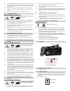
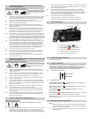
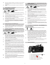
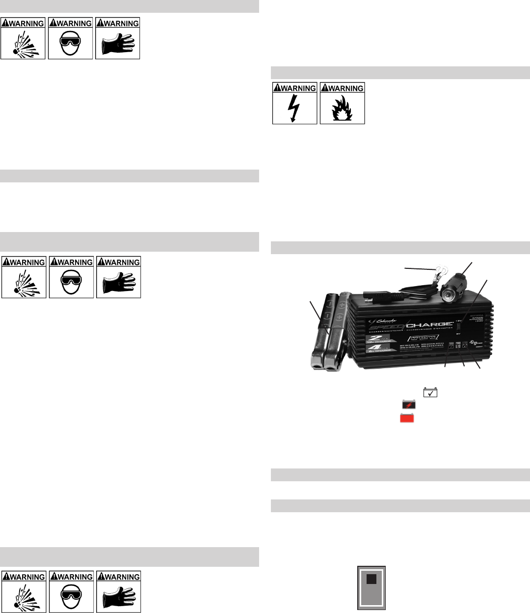
FEATURES9.
Amp/Volt Selector Switch1.
CHECKBATTERY2.
(red)LED
CHARGING 3. (yellow)LED
CHARGED 4.
(green)LED
Battery Clip Cable Assembly5.
Ring Terminal Cable Assembly6.
12V Plug Cable Assembly7.
3
4
5
7
6
1
2
ASSEMBLY INSTRUCTIONS10.
No assembly required
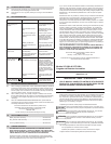
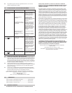
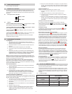
CONTROL PANEL11.
The charger does not have an ON/OFF switch. The On and Off commands are
controlled by plugging the charger into a 120V AC electrical wall outlet only
after the battery connections have been made and the Amp/Volt selector switch
has been set.
Amp/Volt Selector Switch11.1
2 Amp, 12 Volt
4 Amp, 6 Volt