


2
Sch590
PREPARING TO CHARGE
C
1. Make sure you have a 12 volt lead-acid battery. Check car
owner manual to make sure.
2. Clean battery terminals. Take care to keep corrosion from
coming in contact with your eyes.
3. If required, add distilled water in each cell until battery acid
reaches levels specified by battery manufacturer. This helps
purge excessive gas from cells. Do not overfill. For a battery
without cell caps, carefully follow manufacturer's recharg-
ing instructions.
4. Study all battery manufacturer's specific precautions, such
as removing or not removing cell caps while charging, and
recommended rates of charge.
5. Be sure area around battery is well ventilated while battery
is being charged. Gas can be forcefully blown away by us-
ing a piece of cardboard or other non-metallic material as a
fan.
6. If necessary to remove battery from vehicle to charge, al-
ways remove grounded terminal from battery first. Make sure
all accessories in the vehicle are off, so as not to cause an
arc.
7. A marine (boat) battery must be removed and charged on
shore. To charge it on board requires equipment specially
designed for marine use.
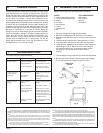
8. Select charge rate suitable for the battery being charged -
(2 or 40 Amps)
Grounding methods
GROUNDING AND AC POWER CORD CONNECTION IN-
STRUCTIONS - Charger should be grounded to reduce risk of
electric shock. Charger is equipped with an electric cord having
an equipment-grounding conductor and a grounding plug. The
plug must be plugged into an outlet that is properly installed and
grounded in accordance with local codes and ordinances.
DANGER - Never alter AC cord or plug provided - if it will not fit
outlet, have proper outlet installed by a qualified electrician. Im-
proper connection can result in a risk of electric shock.
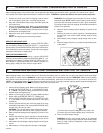
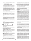
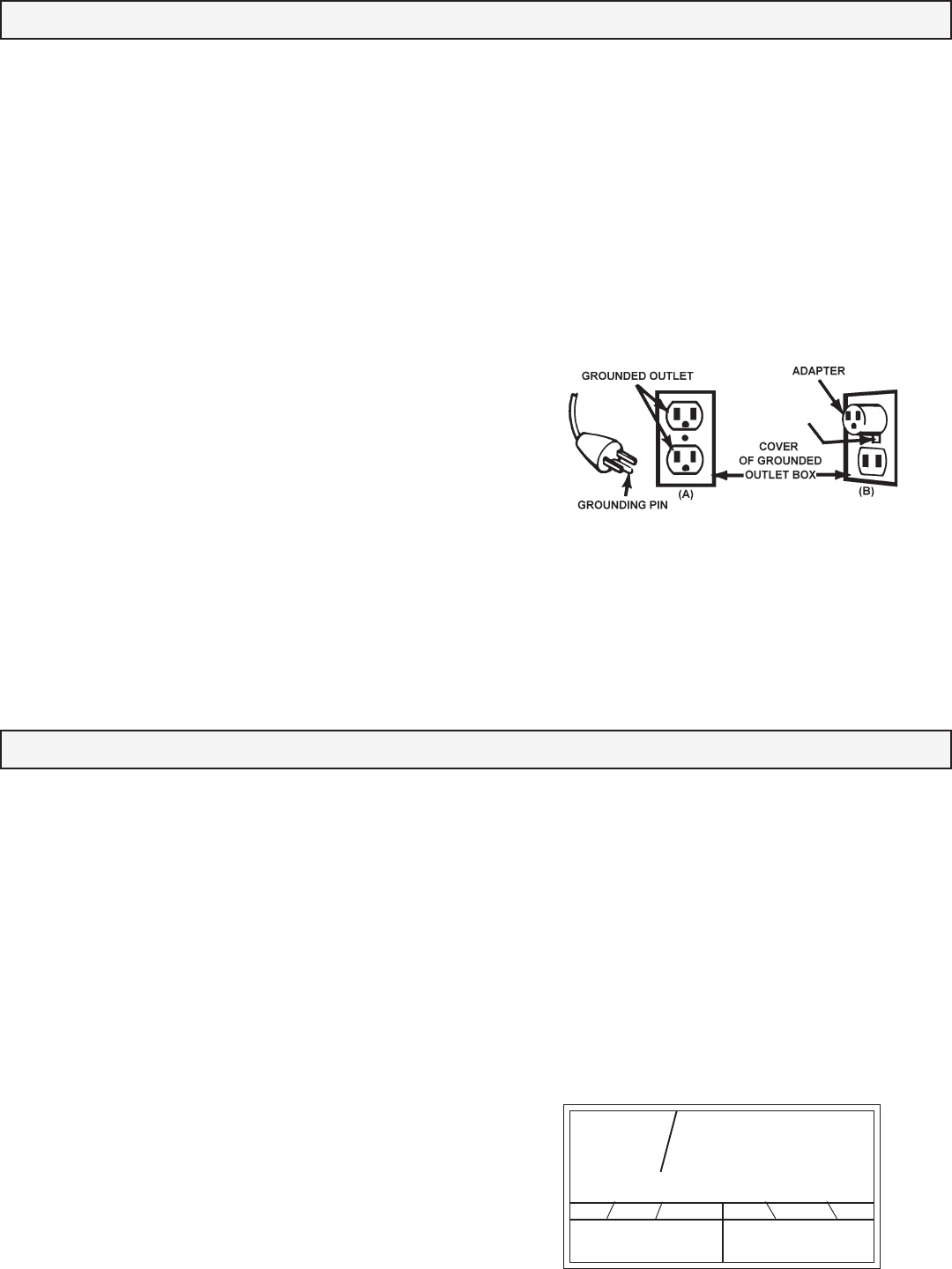
This battery charger is for use on a nominal 120-volt circuit, and
has a grounding plug that looks like the plug illustrated in sketch
A. A temporary adapter, which looks like the adapter illustrated
in sketch B, may be used to connect this plug to a two-pole re-
ceptacle as shown in sketch B if a properly grounded outlet is
not available. The temporary adapter should be used only until a
properly grounded outlet can be installed by a qualified electri-
cian.
DANGER - Before using adapter as illustrated, be certain that
center screw of outlet plate is grounded. The green-colored rigid
ear or lug extending from adapter must be connected to a prop-
erly grounded outlet - make certain it is grounded. If necessary,
replace original outlet cover plate screw with a longer screw that
will secure adapter ear or lug to outlet cover plate and make
ground connection to grounded outlet.
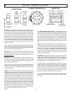
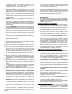
MULTI FUNCTION TEST METER
This meter responds to voltage, not current. It has been di-
vided into two scales designated Battery/Tester and Alternator
/Charger. Each scale is further divided into three color zones,
(red, yellow, and green).
USING THE METER AS A TESTER
1. Since this test is based on terminal voltage of the battery,
always begin with a fully charged battery. The battery must
be installed in vehicle, with the engine and accessories turned
off.
2. There is no need for the charger to be connected to the AC
power.
3. Connect charger to battery as described in para. E.
4. The meter pointer should be within the green zone of the scale
designated Battery/Tester. If the battery has just been
charged, the pointer may be past the green zone and into the
yellow zone of the alternator scale. This is normal. If the
pointer rests in the red or yellow zone of the Battery/ Tester
scale, the battery may need to be charged.
5. While connected to the battery, turn on the vehicle headlights
for approximately 10 minutes, then observe the meter read-
ing. For a good battery (the pointer will initially move towards
VOLT METER FUNCTIONS
D
● BAD ● WEAK ● GOOD
12 VOLT BATTERY
Battery
Tester
the yellow side of the green zone, then remain fairly con-
stant throughout remainder of the test. If the pointer contin-
ues to move and falls into the yellow or red zones it indicates
a weak battery and a potential problem. For heavy duty bat-
teries, more accurate results may be obtained by extending
the time a few minutes.
CHECKING THE VEHICLE CHARGING SYSTEM
1. Follow instructions 1 thru 4 of the battery test section.
2. Start Engine: If the vehicle charging system is working prop-
erly, the meter pointer should be within the green zone of the
scale designated Alternator/Charger. If the pointer is in the
yellow zone, it is likely that the alternator is not charging the
battery. If the pointer rises to the extreme right hand side of
the red zone it’s likely that the battery is being overcharged.
Alternator
Charger
METAL SCREW
RYGn Y GnR