


5
Sch590
SCHUMACHER ELECTRIC CORPORATION, 801 BUSINESS CENTER DRIVE, MOUNT
PROSPECT, ILLINOIS 60056-2179 MAKES THIS LIMITED WARRANTY TO THE ORIGINAL PUR-
CHASER AT RETAIL OF THIS PRODUCT. THIS LIMITED WARRANTY IS NOT TRANSFER-
ABLE.
Schumacher Electric Corporation warrants this battery charger for three years from date of
purchase at retail against defective material or workmanship. If such should occur, the unit will be
repaired or replaced at the option of the manufacturer. It is the obligation of the purchaser to
forward the unit together with proof of purchase, transportation and/or mailing charges prepaid to
the manufacturer or its authorized representative.
This limited warranty is void if the product is misused, subjected to careless handling, or
repaired by anyone other than the manufacturer or its authorized representative.
The manufacturer makes no warranty other than this limited warranty and expressly ex-
LIMITED WARRANTY
cludes any implied warranty including any warranty for consequential damages.
THIS IS THE ONLY EXPRESS LIMITED WARRANTY AND THE MANUFACTURER NEI-
THER ASSUMES NOR AUTHORIZES ANYONE TO ASSUME OR MAKE ANY OTHER OBLIGA-
TION TOWARDS THE PRODUCT OTHER THAN THIS EXPRESS LIMITED WARRANTY. THE
MANUFACTURER MAKES NO WARRANTY OF MERCHANTABILITY OR FITNESS FOR PUR-
POSE OF THIS PRODUCT AND EXPRESSLY EXCLUDES SUCH FROM THIS LIMITED WAR-
RANTY.
SOME STATES DO NOT ALLOW THE EXCLUSION OR LIMITATION OF INCIDENTAL OR
CONSEQUENTIAL DAMAGES OR LENGTH OF IMPLIED WARRANTY SO THE ABOVE LIMI-
TATIONS OR EXCLUSIONS MAY NOT APPLY TO YOU.
THIS WARRANTY GIVES YOU SPECIFIC LEGAL RIGHTS AND YOU MAY ALSO HAVE
OTHER RIGHTS WHICH VARY FROM STATE TO STATE.
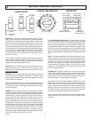
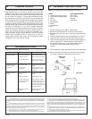
CHARGE PERIOD
The approximate time required to bring a battery to a full charge
state depends upon the number of ampere hours (AH’s) de-
pleted from the battery. AH’s are determined by multiplying the
number of hours times the number of amps supplied by a bat-
tery to a load. For example - if a load was connected to a bat-
tery which drew 10 Amps for a period of 5 hours, the battery will
have supplied 50 AH’s. The approximate recharge time required
to restore the 50 AH’s depleted from the battery would be cal-
culated by dividing 50 AH’s by the selected charge rate. If the
40 Amp charge rate is chosen then divide 50 AH’s by 40 Amps,
this equal to 1.25 hours or 1 hour and 15 minutes. During the
charge cycle, the 40 Amp charge rate will not remain constant,
rather as the battery charges it will taper to approximately 15
Amps. Also not all of the energy going into the battery is di-
rectly converted, some is lost in the form of heat. For these
reasons allow an additional 25% in charge time. For this ex-
ample add 20 minutes to the 1 hour and 15 minutes for a total
recharge time of 1 hour and 35 minutes.
H
TROUBLESHOOTING
If a problem does occur, check the following:
PROBLEM POSSIBLE CAUSE SOLUTION
No meter reading. Clips are not making Rock clips back and
a good connection forth for a better connection.
AC Cord Unplugged. Plug AC line into outlet.
Meter should now indicate.
Charger will not turn AC outlet is dead. Plug in a lamp to check for
on when properly voltage.
connected. Poor electrical Check connectors, rock
connection. back and forth for a better
connection.
Clicking noise from Circuit breaker is May be in the wrong switch
charger. cycling. position.
Battery is defective. Have Battery checked.
Severely discharged Allow charging to continue
battery but otherwise until battery has a chance
a good battery. to recover sufficiently to take
a charge. If more than 20
min. stop charging and have
the battery checked.
Reverse connections Shut off charger and correct
at battery. lead connections.
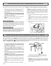
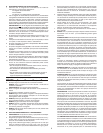
ASSEMBLY INSTRUCTIONS
NOTE: Unit must be fully assembled before operating.
PARTS: TOOLS NECESSARY:
2 10-32 thread cutting screws 3/8" wrench
2 1/4-20 thread cutting screws 5/16" wrench
2 wheels Hammer
2 axle caps screwdriver
2 axle brackets
1 handle
1 mounting foot
1 axle
1. Place the charger on its side on a flat surface.
2. Mount the mounting foot FIG. A with (2) 1/4-20 screws.
3. Next pound the axle firmly into an axle cap using a hammer
FIG. B.
4. Slide the wheels onto the axle, hubs must face in, FIG. C.
5. Pound the other axle cap onto the other end of the axle.
6. Place the axle assembly onto the bottom of the charger as
shows in figure FIG. C. Mount the axle to the bottom of
the charger using the two 10-32 thread cutting screws
as shown in Fig. D (these screws require a 5/16"
wrench.)
7. Turn the battery charger right side up onto its foot and wheels.
8. Remove the two top screws from each side of the charger,
line up the handle and reinstall the screws. FIG. E.
I
J
Fig. B
Fig. A
HUBS MUST
FACE IN
Fig. C
Fig. D
Fig. E
AXLE CAP
AXLE