


assembly
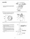
MOUNTING BAND SAW/SANDER ON LEG SET
NOTE: For illustrative purposes, the Band Saw is shown
mounted on the Craftsman Catalog No.9-22236 Steel *Leg
Set. This Leg Set is included with Model No. 113.243311.
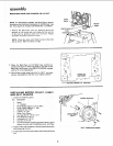
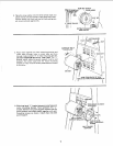
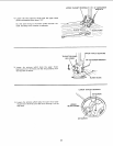
1. Remove the Band Saw cover by applying gentle side
pressure on the spring tabs and release the top portion
of the cover by pulling it away from the frame. Repeat
procedure for bottom portion of cover
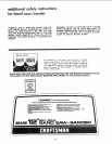
NOTE: Check the bolts which hold the feet to the Band
Saw as shown. Make sure they are tight.
LE FT
FOOT \
CHECK BOLTS
FOR
TIGHTNE_
RIGHT
FOOT
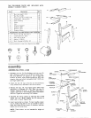
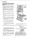
2. Place the Band Saw on the Steel Legs, position as
shown and align the mountmg holes in the feet of the
Band Saw with those in the END STIFFENERS (marked
with an X in the illustration),
3, Mount saw to legs using four (4) 5/16-1BXl " hex head
screws, Iockwashers, and hex nuts. Tighten screws.
©
0 0
°° 0
©
©©
o o
o 0 0
0 o
0 o
Oo
0
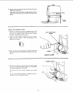
FRONT OF
SAW HERE 0o0
MOTOR SUPPORT AT THIS END
iNSTALLING MOTOR, PULLEY, V-BELT,
AND BELT GUARDS
1. Locate the following parrs:
Qty. Description
1 Motor
1 -L'" Bracket
1 Small Pulley (approx. 2-1/2" Dia.)
1 Large Pulley (approx. 5" Dia )
1 Woodruff Key 3/16"'
1 V-Belt 1/2 x 52
1 Motor Cord Clamp
4 Carnage Bolt 5/16-18 x 3/4
4 Flat Washer 5/16 I.D.
4 Lockwasher 5/16 I.D.
4 Hex Nut 5/16-18
2 Guard Assembly including a guard support, guard
support bracket, self-threading screws, and clips,
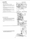
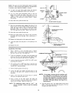
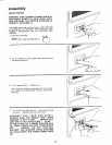
2. Fasten a belt guard support to the band sawframewith
self-threading screws
3. Install clJ ps onto the guard support with long end facing
you.
_ARD SUPPORT
"_._./_ / /2_ __-.N\l
SHAFT __-_
/
/
SELF-THREADING SCREW