


20
OPERATION cont.
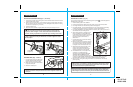
!
Make sure to insert the accessory bit straight into the chuck
jaws. Do not insert the accessory bit into the chuck jaws at an angle then
tighten, as shown in Figure 13. This could cause the bit to be thrown from
the drill, resulting in possible serious personal injury or damage to the chuck.
WARNING:
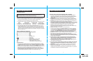
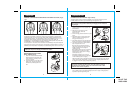
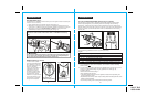
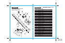
INSTALLING ACCESSORY BITS (Figs. 11, 12 and 13)
1. Lock the trigger switch Off by placing the Forward / Reverse Selector Switch with Power
Lock-Off in the Center position.
2. Open or close the chuck jaws to a point where the opening is slightly larger than the bit
size you intend to use. Also, raise the front of the drill slightly to keep the bit from falling
out of the chuck jaws (see Fig. 11 and 12).
3. Insert the accessory bit.
4. Rotate the chuck clockwise to tighten (GRIP) the chuck jaws securely on the bit.
Fig. 11
Fig. 12
NOTE: Rotate the chuck body in the direction of the “HAND POINTING” marked
“GRIP” to tighten the chuck jaws. DO NOT use a wrench to tighten or loosen
the chuck jaws.
5
7
3
1
9
C
o
m
p
a
n
i
o
n
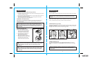
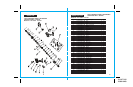
REMOVING BITS
(Figs. 11 and 12)
1. Lock the trigger switch Off by placing the
Forward / Reverse Selector Switch with
Power Lock-Off in the Center position.
2. Rotate the chuck body counterclockwise
to open the chuck jaws.
3. Remove the accessory bit.
NOTE: Rotate the chuck body in the direction of the HAND POINTING marked
RELEASE to loosen the chuck jaws. DO NOT use a wrench to tighten or loosen the
chuck jaws
.
Fig. 13
5
7
3
1
9
C
o
m
p
a
n
i
on
9.
6 V
COUNTER-CLOCKWISE
(Release Bit)
WRONG
OPEN JAWS
(insert bit)
CLOSE JAWS
(to tighten bit)
5
7
3
1
9
C
o
m
p
ani
o
n
CLOCKWISE
(Grip Bit)
10-4-07 Drill
10300-10400
21
OPERATION cont.
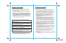
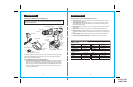
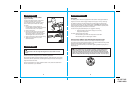
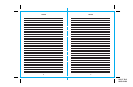
OPERATION AS A DRILL (Fig. 14)
Turn and set the torque clutch collar to the drilling position symbol . Install and tighten the
desired drill bit into the chuck.
1. Install the battery pack into the drill/driver.
2. Push the forward/reverse selector switch with power lock-off to the forward position.
3. For drilling in WOOD, use twist drill bits, spade bits and auger bits.
4. For drilling in METAL, use high speed twist drill bits. Use a cutting lubricant when drilling
in metals. The exceptions are cast iron and brass, which should be drilled dry.
5. For drilling in MASONRY, use carbide tipped bits or masonry bits. A smooth, even flow of
dust indicates the proper drilling speed.
6. Always apply pressure in a straight line with
the bit. If necessary, use the bubble levels
to drill straight into the workpiece. Use enough
pressure to keep the bit biting, but do not
push hard enough to stall the motor or
deflect the bit.
7. Hold drill/driver firmly to control the twisting
action of the drill/driver.
8. Move the drill bit into the workpiece, applying
only enough pressure to keep the bit cutting.
Do not force the drill or apply side pressure
to elongate a hole. Let the tool do the work.
9. When drilling hard, smooth surfaces, use a
center punch to mark the desired hole
location. This will prevent the drill bit from
slipping off-center as the hole is started.
10. If the drill/driver stalls, or the bit jams in the
workpiece, it is usually because the
drill/driver is being overloaded. RELEASE
TRIGGER SWITCH IMMEDIATELY and
remove bit from workpiece. Determine cause
of stalling. DO NOT PRESS TRIGGER OFF AND ON IN AN ATTEMPT TO START
A STALLED DRILL/DRIVER – THIS COULD DAMAGE THE DRILL/DRIVER.
11. Keep the motor running when pulling the bit back out of a drillled hole. This will help
prevent jamming.
!
Be prepared for binding at bit breakthrough. When these situations
occur, drill/driver has a tendency to grab and kick opposite to the direction of rotation
and could cause loss of control when breaking through material. If not prepared, this
loss of control could result in possible serious injury.
WARNING:
NOTE: This drill/driver has an electric brake. When the trigger switch is released, the
chuck stops turning instantly. When the brake is functioning properly, sparks will be
visible through the vent slots on the housing. This is normal and is the action of the brake.
Fig. 14
C
om
p
a
n
i
o
n