


NORMAL iNSTALLATiON STEPS
Step t
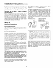
Provide Adequate Gas Supply
The range is designed to operate at a pressure of 4
inches of water column on natural gas or, if designed
for LP gas (propane or butane), 10 inches of water
column. Make sure the range is supplied with the type
of gas for which it is designed. If, at any time in the
future, the range is to be supplied with a different type
of gas, conversion adjustments must be made by a
qualified service technician before attempting to oper-
ate the range on that gas.
For proper operation, the pressure of natural gas sup-
plied to the regulator must be between 4 and 13 inch-
es of water column. For LP gas, the pressure supplied
must be between 10 and 13 inches of water column.
When checking for proper operation of the regulator,
the inlet pressure must be at least 1 inch greater than
the operating (manifold) pressure as given above. The
pressure regulator located at the inlet of the range
manifold must remain in the supply line regardless of
whether natural or LP gas is being used. A flexible
metal appliance connector used to connect the range
to the gas supply line should have an I D. of 1/2" and
be 5 feet in length (shorter and longer lengths are
acceptable) for ease of installation.
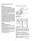
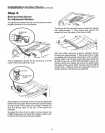
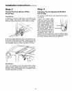
Step 2
Connect the Range to Gas
Before disconnecting the old range, shut off the main
gas supply valve and leave it off until new hook-up
has been complete&
Because hard piping restricts movement of the range,
the use of an A.G.A._certified flexible metal appliance
connector is recommended unless local codes require
a hard-piped connection. Never use an old connector
when installing a new range°
To prevent gas leaks, wrap pipe thread tape with
"Teflon* around, or put pipe joint compound on, all
mate (external) pipe threads.
*Teflon: Registered trademark of DuPont
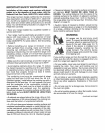
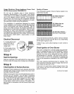
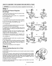
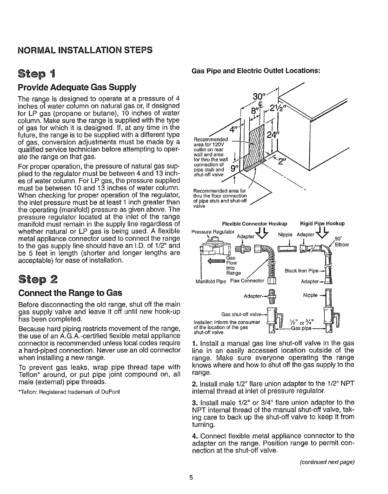
Gas Pipe and Electric Outlet Locations:
Recommended
area for 120V
outlet on rear
wail and area
for thru the waft
connection of
pipe stub and
shut-off valve
Recommended area for
thru the floor connection
of pipe stub and shut-off
ValVe
Flexible Connector Hookup Rigid Pipe Hookup
Pressure Regulator J _ 4_ 7
_,_=_ AdapterV Nipple Adapter -,. __
9U"
Adapter Nipp e
Gas shut-off vaive--_ ]_i} ] |[_
Installer: Inform the consumer _ ill 1A" or 3_,, ,L.:.t!,ltt
of the location of the gas I_Gas pioe_ _
shut-off valve L<_ - - b_
1. Install a manual gas line shut-off valve in the gas
line in an easily accessed location outside of the
range. Make sure everyone operating the range
knows where and how to shut off the gas supply to the
range
2. Install male 1/2" flare union adapter to the I/2" NPT
internal thread at inlet of pressure regulator.
3. Install male 1/2" or 3/4" flare union adapter to the
NPT internal thread of the manual shut-off valve, tak-
ing care to back up the shut-off valve to keep it from
turning
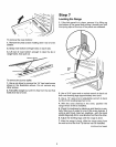
4. Connect flexible metal appliance connector to the
adapter on the range, Position range to permit con-
nection at the shut-off valve,
(continued next page,)