


ASSEMBLY INSTRUCTIONS
Tools Needed for Assembly
* pipethreadsealant(not incJuded)
, an a,clJustable wrench for attaching the pressure
regulator
" a _t_0,socket or open end wrench for attaching the
wheelsand hose adaptan
" a 7/1_openand wrench for attaching the air pressure
gauges
, a _e °'he,v.Re'i"for Installing the pluginthe regulal_
, a %" open end wrenchto tightenhandlescrews
"s #2 philtipe screwdriver for attaching the control
cover
installing Wheels, Handle, Rubber Foot Strip
i WARNIN_ !
THE WHEELS AND HANDLE OO NOT PRO-
VIDE ADEQUATE CLEARANCE, $TABJLITY
OR SUPPORT FOR PULLING THE UNIT UP
AND DOWN STAIRS OR STEPS, THE UN[T
MUST I_ELtFT]_D, ORPUSHED UP A RAMP.
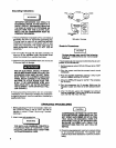
1. Dipthe handle grip Insoapywater and sttdeintoposi-
tionas shownon photoon page 6 orpage 12.
2, Attachthe handleto the insideofthecompressorsad-
diebyp_jshtngthe handleIn,unllitheslotinthehandle
engageswith the labs in the saddle,Pufithe handle
bsckar<l installthe two s<z_ws,one oneach sideof
the _e_ldte.Tightensecurely,
ittory be necemury to brace or support one
enU of the outfit when attaching the wheels
end the r_Jbber foot _trlp,because the air
compressor will have a tenden=y to tip.
3- Rsmove the protectivepaperstrip frOmth_ adhesive
backed rubber footstrip,Attachtherubberfootstrip to
the bottom of 1heairtitnkleg. Press firmlyinto place°
4. Attachone wheelto each sideof theair ¢omp_ssor.
Use one shoulder bott and one nut for each wheel,
Tighten securely.
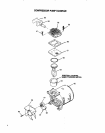
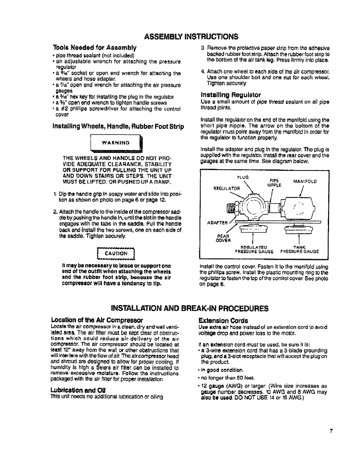
Installing Regulator
Use a small amountof,pipe thread sealant on aJipipe
thread joints.
Installthe regulatoron 1heendof lhe manifold using the
short pipe nipple. The arrow on the bottom ol the
regulatOrmust poi_ away from the manifold in order fo_
theregulatortofunctionproperly,
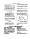
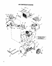
_nstalithe adapter and plugIn the regulator,,The plugis
supplied withthe regulator,Installthe rearcoverandthe
gauges at the same time,See diagrambelow,
R_ULATED
PRESSURE GAUG_
TANK
PRESSURE GAUGP-
tnstallthe control_over. FastenIt to the manifoldusing
the phillipsscrew.Installthe plasticmounting ringtothe
regulatortofastenthetopofthecontmtcover,See photo
on page 6.
INSTALLATION AND BREAK-IN PROCEDURES
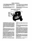
Locationof the Air Compressor
Loca4ethe air compressorina ctean,dry endwelJventi-
lateclarea. The air filler must be kept clearo'l obstruc.
tlons which could reduce air delivery of the air
compressor.The air compressorshould be locatedat
least 12' away'fromthe wail or other obstructionsthat
wl!linterfere withtheftow of air. Theaircompressorhead
and shroudare designed to al!ow forpropercooling.,If
humidity Is high a _ears air filter can be installed iD
remove excessive moisture. Follow the instructions
packaged withthe air filter for proper installation,
LubricationandOil
Thtsunit n_eas no adcllttonal lubrication or otling
Extension Cords
Use extre,air hose insteaxJOf _nextensioncordto avoid
voltagedrop and power loss to the motor,
tf an axlet_slon cordmustt_ us'_, be sum it is:
. a 3-wire ext_._ion cord thath_ a _-,blade grounding
pll_, end !_3-_lotreceptacletigatwl!laccepttheplugon
the product,
. t_ good condition_
• no longerthan _50f_t.
.12 gtlUge (AWG) or larger. (Wire size increases as
gauge number _lecreaseso10 AWG and 8 AWG may
atso l_eused,OO NOT USt_t4 or 16AWG_)