


2
SAFETY
Hypot Testing
Each 8800ES series tool that is serviced must be
Hypot tested before being shipped back to the
customer. If you do not have this equipment, you
can not service this tool.
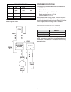
Hypot testing is a safety test required by Underwriters
Laboratories. It basically ensures that there are no live
metal parts exposed on the product. This condition could
occur if, for instance:
1. A housing screw went through a wire.
2. A wire was stripped back too far and the bare wire
contacted a bearing or the driveshaft.
3. A wire was damaged and came into contact with a
bearing or the driveshaft.
This is a very serious safety issue so please take care to
test the tool as specified below.
The tool is to be Hypot tested at 3000 VAC for 1
second between:
A. Both power cord prongs and the chuck with the
power switch in the ON position.
B. Between the power cord prongs and all of the
housing screws with the power switch in the ON
position.
The maximum allowable current is 0.5mA.
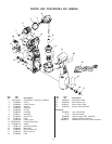
REPAIR
The following are specific instructions for repairing the
8800ES drill. For a list of available service parts and an
exploded-view product drawing, please refer to the last
page of this manual.
These repair instructions start with the very basic repairs
such as replacing a chuck and progress to the more
complicated such as replacing a housing. They are done
this way so all of the information does not have to be
repeated. For this reason you may want to read the entire
instruction before proceeding with one of the more compli-
cated repairs.
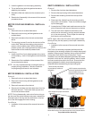
CHUCK REMOVAL / INSTALLATION
Removal
1. Open chuck jaws to maximum capacity.
2. Remove retaining screw on tool by turning it in a
clockwise direction (screw has a left-hand thread).
3. Insert the shorter end of a 1/4 or greater hex key into
chuck and tighten.
4. Place tool on its side and hold firmly.
5. Using a wooden mallet strike the longer end in the
clockwise direction.
Installation
1. Screw the chuck on by hand as far as it will go.
2. Insert screw (left-hand thread), and tighten screw se-
curely.
3. Tighten the chuck around the shorter end of a 1/4 or
larger hex key, then strike the longer end in the clockwise
direction with a wooden mallet while holding down the tool
securely.
4. Tighten the screw once again by turning in a counterclock-
wise direction.
BRUSH REMOVAL / INSTALLATION
Removal
1. Remove brush cap using a flat-head screwdriver.
2. Remove brush assembly from the brush holder.
Installation
1. Installation is the reverse of the removal instruction
above.
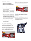
GEARBOX REMOVAL / INSTALLATION
Currently, the gearbox components are not individually
available, and in the event of a failure, the entire gearbox
must be replaced.
The procedure for removing / installing the gearbox is as
follows:
Removal
1. Remove the chuck as described above.
2. Remove the brush caps and take out the brushes.
The brushes should always be removed before
disassembling the housing.
3. Remove the (8) housing screws and remove the right
housing half. While removing the right housing half,
disconnect the yellow brush lead from the brush
holder. This can usually be disconnected with your
fingers. If not, a needle-nose pliers will suffice.
4. Remove the chuck shroud.
5. Lift up the gearbox so that the motor assembly tips
upward. Once the gearbox is above the left housing
half, pull it away from the motor so the input shaft
pulls out of the motor coupling.
Installation
1. Remove the armature while leaving the field in place.
In order to remove the armature, you will have to tip
up the field so that the fan clears the housing.
2. Ensure that there is grease in the motor coupling and
that the o-ring is in place in the end of the coupling. If
grease must be added, a light film of any moly based
grease will be adequate.
SERVICE INSTRUCTIONS FOR MODEL NO. 8800ES
WARNING
Disconnect power before doing any repairs!