


3
3. Insert the gearbox into the coupling assembly.
4. Tip up the field and slide the gearbox/armature
assembly into location.
5. Reseat the field and make sure the armature spins
freely.
6. Remainder of assembly is the reverse of the removal
procedure above.
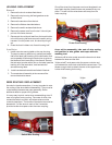
MOTOR COUPLING REMOVAL / INSTALLA-
TION
Removal
1. Remove the chuck as described above.
2. Remove the top housing half and gearbox as de-
scribed above.
3. Remove the armature from the tool as described
above.
4. The coupling is press fit onto the knurled end of the
motor shaft. Remove the coupling using an arbor
press or other suitable press. With the armature
pointed upward, the coupling should be held from the
bottom side and the armature pressed down.
Installation
1. Install a light film of moly based grease to the inside
of the coupling both in the large and small diameter
bores.
2. Remainder of the installation is the reverse of the
removal instruction above.
NOTE: It is very important that the coupling be lined up
properly during installation. Failure to install the
coupling straight will result in tool vibration.
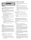
MOTOR REMOVAL / INSTALLATION
Removal
1. Remove the chuck as described above.
2. Remove the top housing half and gearbox as de-
scribed above.
3. Remove the armature from the tool.
4. Disconnect the black and white lead wires from the
field and remove it. The thicker black jumper wire
should not be disconnected
NOTE: During disassembly, take note of wire routing so
the wires can be routed the same way upon reassembly.
Also take note of the way the two dowel pins on the fan
end of the field engage the lower housing.
Installation
1. Installation is the reverse of the removal instruction
above.
SWITCH REMOVAL / INSTALLATION
Removal
1. Remove the chuck as described above.
2. Remove the top housing half as described above.
3. Remove the reversing shuttle from the top of the
switch.
4. Disconnect the 4 leads from the reversing module
(top portion) of the switch. These should slide straight
up and disengage.
5. Loosen the two Phillips head machine screws on the
side of the switch and remove the power cord wires.
6. The red brush wire installed in the bottom of the
switch can be removed by pushing a small diameter
pin in the wire opening. This will open the wire trap
and the wire can be pulled out.
NOTE: Again, take note of the wire routing before disas-
sembly so they can be properly routed upon reassembly.
Installation
1. Installation is the reverse of the removal instruction
above.
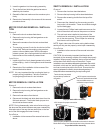
CAUTION: It is extremely important that the wires that
terminate in the reversing module of the switch be properly
installed. When properly installed, the top of the terminals
will be about flush with the top of the switch. Proper
installation ensures adequate spacing between the switch
terminals, which are live, and the gearbox, which is metal
and has a conductive path to the chuck. Ensure that the
spacing between the switch terminals and gearbox is
adequate before reassembling the top housing half.
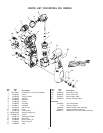
Improper Switch Wire Assembly
Terminals may not extend
beyond the top surface of
the switch.
100% inspect to see that the
terminal is pushed down all the
way and that there are no
excessive lumps of solder.
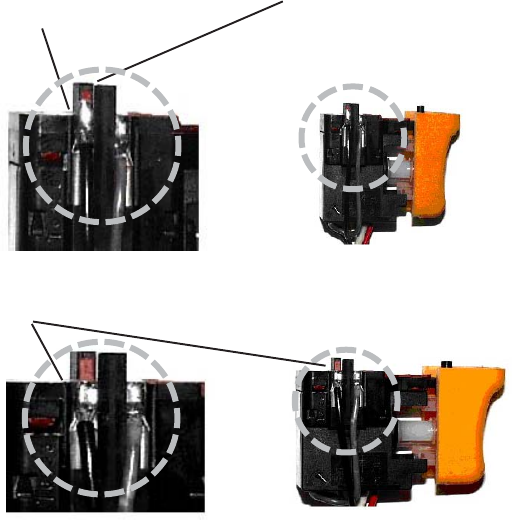
When properly installed, the terminals on the switch wires are
fllush with the top of the switch as shown in the pictures above.
Proper Switch Wire Assembly
100% inspect for proper connection.