


4
HOUSING REPLACEMENT
Removal
1. Remove the chuck as described above.
2. Remove the top housing half and gearbox as de-
scribed above.
3. Remove the armature from the tool.
4. Remove the field as described above
5. Remove the switch as described above.
6. Remove the power cord from the tool. It should just
pull out of the wire channel.
7. Disconnect the red brush lead from the brush holder
in the left housing half and remove the switch wiring
harness. Like the power cord, this should pull right
out.
8. Press the brush holders out of each housing half.
Installation
1. Install a service warning label on the new housing.
The service warning label is only partially laminated.
Half of the label has a backing on the lamination that
can be peeled off allowing the technician to write on
the label and finish laminating it him/herself. Record
the tool serial number with a pen on the label, peel the
backing off of the lamination, and laminate the
service warning label.
2. Install new decorative and brand labels if desired.
3. The remainder of assembly is the reverse of the
removal instruction above.
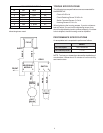
WIRE ROUTING / REPLACEMENT
As noted in the above sections, it is very important to note
the routing of the wires before disassembly. They must be
routed exactly the same way upon assembly. Some
additional detail on proper wiring follows.
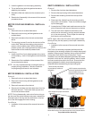
It is very easy to pinch a wire when reassembling a tool if
care is not given to wire routing. Take note of which ribs
contact the switch and field, and where wires must be
routed to clear them. The bundle of 4 switch wires must be
placed with 2 of the wires in each of the 2 wire slots
provided as the wires pass under the motor coupling.
One of the wires from the power cord must be placed in on
top of each bundle of switch wires and pressed firmly into
place. This will hold the wires down and away from the
motor coupling.
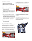
As an aid to reassembly, take note of wire routing
and position in wire guides and traps while dis-
mantling tool.
White wire #5 is to be routed around the lower brush boss
between the boss and the field.
Yellow wire #7 must pass under the power cord wire and
exit between the cord strain relief and the screw boss. This
allows enough slack to attach the wire to the upper brush
holder while lowering the housing.
Switch Wire Routing
Power Cord Routing
Yellow
White