


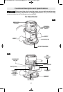

Skil routers are designed for speed, accuracy
and con venience in performing cabinet work,
routing, fluting, beading, cove-cutting, dove
tails, etc. They will enable you to accomplish
inlay work, decorative edges and many types
of special carving.
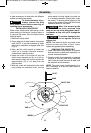
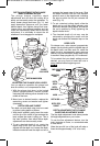
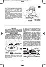
DEPTH ADJUSTMENT WITH FIXED BASE
FINE ADJUSTMENT KNOB
The fine adjustment knob allows precise bit
height adjustments on your router.
To use the fine adjustment feature, release the
base clamp lever, and turn the knob clockwise
to lower, or counterclockwise to raise the bit
(Fig. 2).
(Note that one full turn of the knob will raise or
lower the bit approximately 1/16" of an inch.)
After making depth adjustments, re-clamp the
motor.
NOTE: All depth adjustments must be made
with the base clamp lever released.
DEEP CUTS
For deeper cuts, make several progressively
deeper cuts by starting at one depth and then
make several subsequent passes, increasing
the cutting depth with each pass.
To be certain that your depth settings are as
desired, you may want to make test cuts in
scrap material before beginning work.
Operating Instructions
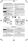
CHIP DEFLECTOR
Always wear eye protection.
The chip deflector is not
intended as a safety guard.
The chip deflectors help keep dust and chips
out of your face, it will not stop objects larger
than dust thrown from the bit.
To remove chip shield from the fixed base,
press inward on deflector tabs until it releases
from base and remove. To attach, place
deflector into position as shown in (Fig. 10).
Then press inward of deflector tabs while
pushing until it snaps into place.
To remove chip shield from the plunge base,
press inward on either side of the deflector until
it releases from base and remove. To attach,
place deflector into position as shown in
(Fig. 10a). Then press inward of deflector either
side while pushing until it snaps into place.
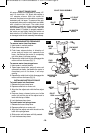
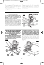
INSTALLING
TEMPLATE GUIDE ADAPTER
(Not included, available as accessory)
Place template guide adapter over the holes
in the center of the sub-base, align the two
threaded holes in the bottom of adapter with
the countersunk holes in sub-base. Fasten
adapter with the screws provided (Fig. 9).
To ensure proper alignment of the template
guide to the armature shaft, a centering cone
(optional accessory) should be used.
-11-
TEMPLATE
GUIDE
ADAPTER
MOUNTING
SCREWS
ROUTER
SUB-BASE
FIG. 9
FIG. 10
!
WARNING
1
1
/
2
1
1
/
2
0
CHIP
DEFLECTOR
CHIP
DEFLECTOR
FIG.
SM 1619X04663 05-11:SM 1619X04663 05-11 5/3/11 8:14 AM Page 11