


-9-
Operating Instructions
VARIABLE SPEED CONTROLLED
TRIGGER SWITCH
Your tool is equipped with a variable speed
trigger switch. The tool speed can be
controlled from the minimum to the maximum
nameplate RPM by the pressure you apply to
the trigger. Apply more pressure to increase
the speed and release pressure to decrease
speed. This accurate speed control enables
you to drill without center punching. It also
permits you to use as a power screwdriver.
Bits are available for driving screws as well as
running bolts and nuts.
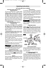
FORWARD/REVERSING LEVER &
TRIGGER LOCK
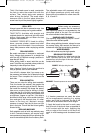
Your tool is equipped with a forward/
reversing lever and trigger lock located above
the trigger (Fig. 1). This lever was designed
for changing rotation of the chuck, and for
locking the trigger in an “OFF” position to help
prevent accidental starts and accidental
battery discharge.
FORWARD/REVERSE INDICATOR LIGHTS
Your tool is equipped with lights which
indicates the rotation of the chuck.
For forward rotation, (with chuck pointed away
from you) move the forward/reversing lever to
the far left and the green indicator will light up
when the trigger is activated.
For reverse rotation move the forward
/reversing lever to the far right and the red
indicator light will light up when the trigger is
activated.
To activate trigger lock move the forward/
reversing lever to the center off position.
Do not change direction of
rotation until the tool comes
to a complete stop.
Shifting during rotation of
the chuck can cause damage to the tool.
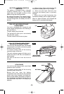
ADJUSTABLE CLUTCH
Your tool features 16 clutch settings. Output
torque will increase as the clutch ring, is rotated
from 1 to 15. The drill “ ” position will lock
up the clutch to permit drilling and driving for
heavyduty work.
BRAKE
When the trigger switch is released it activates
the brake to stop the chuck quickly. This is
especially useful in the repetitive driving and
removal of screws.
INSERTING BIT
For small bits, open jaws enough to insert the
bit up to the flutes. For large bits, insert the bit
as far as it will go. Center the bit as you close
the jaws by hand. This positions the bit
properly, giving maximum contact between the
chuck jaws and the bit shank.
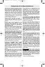
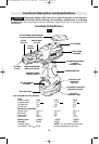
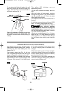
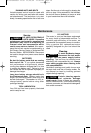
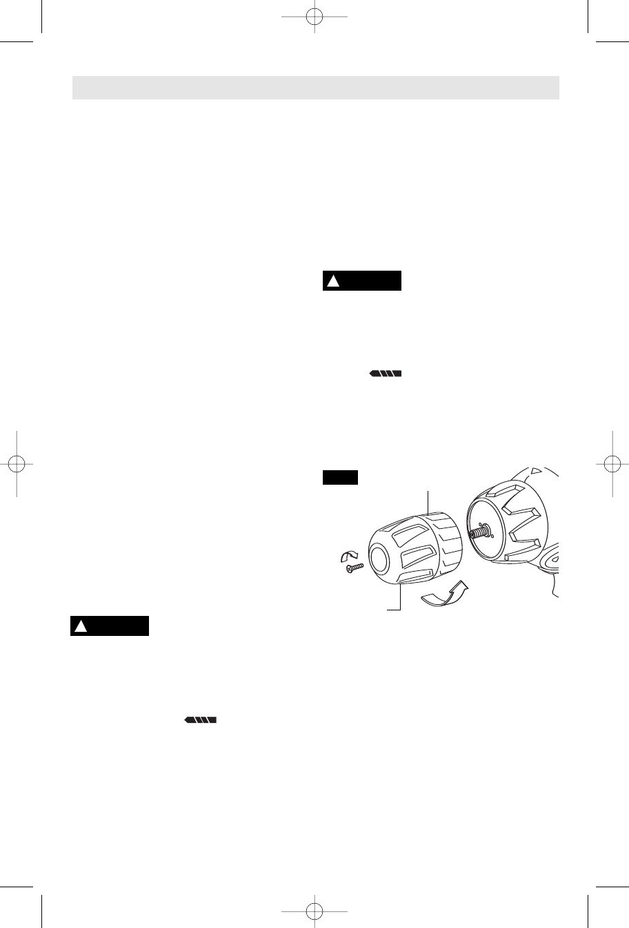
To tighten, hold the chuck collar firmly with one
hand and securely tighten the chuck sleeve
with the other hand (Fig. 2).
Do not use the power of the
drill while grasping chuck to
loosen or tighten bit.
Friction burn or hand
injury is possible if attempting to grasp the
spinning chuck.
REMOVING CHUCK
Rotate the clutch ring to the drill bit
symbol “ ”. Open the chuck all the way,
remove left-hand thread screw inside chuck by
turning it clockwise. Insert the short arm of a
3/8" hex key wrench and close jaws on flats of
wrench. Strike long arm of wrench sharply
counterclockwise, remove wrench and
unthread chuck from spindle (Fig. 2).
INSTALLING CHUCK
Always keep the spindle threads, the threads of
the chuck and securing screw free of debris.
To install a chuck, reverse “removing the
chuck” procedure.
RELEASING AND INSERTING
BATTERY PACK
Release battery pack from tool by pressing on
both sides of the battery release tabs and pull
downwards. Before inserting battery pack,
remove protective cap from battery pack. To
insert battery, align battery and slide battery
pack into tool until it locks into position. Do
not force.
!
WARNING
!
CAUTION
CLOCKWISE
COUNTER
CLOCKWISE
CHUCK
SLEEVE
CHUCK
COLLAR
*
NOT AVAILABLE ON ALL MODELS
FIG. 2
SM 1619X00551 11-04 11/29/04 11:46 PM Page 9