


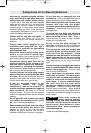
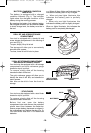
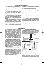
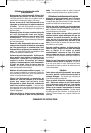
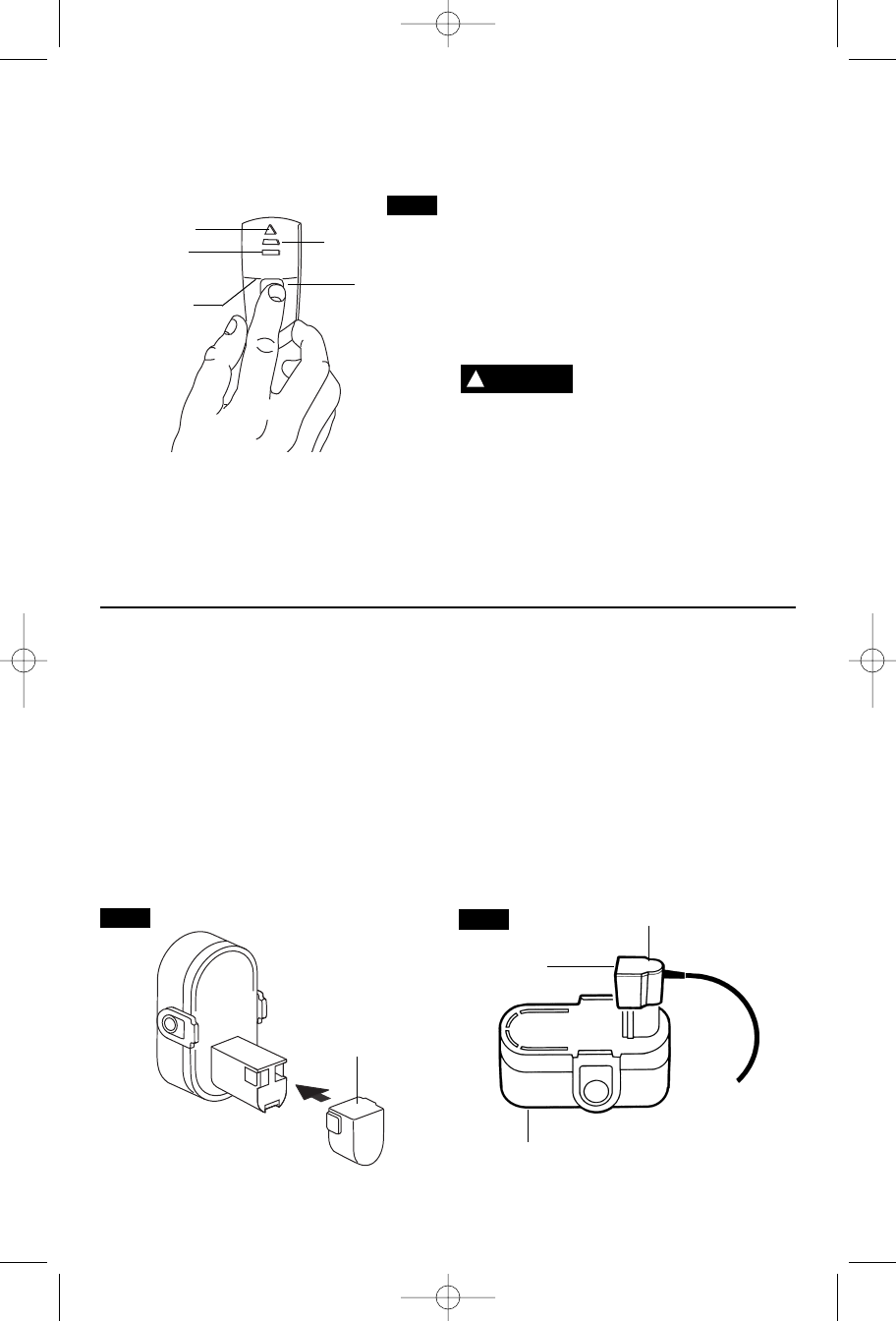
Plug charger cord into your standard power
outlet. Before inserting battery pack, remove
protective cap, then insert battery pack into
charger (Fig. 7).
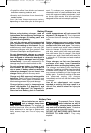
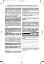
The charger’s green light (Fig. 8), will turn
“ON”. The green light remains ‘‘ON’’ as long as
charger is plugged in, and does not shut off.
After normal usage, the battery pack requires
approximately 3 hours or less charging time
to become fully charged. If the battery pack
is run-down completely, it may require up to
5 hours charging time to become fully
charged.
When the battery pack is fully charged,
unplug the charger (unless you're charging
another battery pack) and slip the battery
pack back into the tool handle.
To prevent fire or injury when batteries are
not in tool or charger, always place protective
cap onto end of battery pack.
INDICATOR
LIGHT
BATTERY PACK
CHARGER
CHARGING BATTERY PACK (3 HOUR CHARGER)
PROTECTIVE
CAP
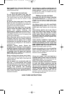
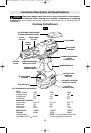
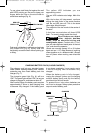
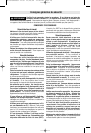
To use, place stud finder flat against the wall
with LEDS pointing up. Be sure to keep your
fingers below the line on the stud finder to
avoid false readings (Fig. 6).
Push and hold button to calibrate and activate
unit (Green LED) (Fig. 6). Slowly slide unit
horizontally across the wall without picking up
or tilting.
The yellow LED indicates you are
approaching a stud.
The red LED indicates stud edge. Mark this
spot.
With the button still depressed, continue
sliding the stud finder in the same direction
until the red LED turns off. This is the studs
other edge. Mark this spot.
The midpoint of the two marks is the center of
the stud.
A fault has occurred when all three LEDS
flash . To correct, simply restart the circuit.
Stud finders can detect
other objects besides
studs, such as electrical wiring and
metal/plastic pipes.
Contact with a “live”
wire will make exposed metal parts of the tool
“live” and shock the operator.
(Studs are normally spaced 16 or 24 inches
apart and are 1-1/2" wide. Beware of anything
closer together or of a different width.) Always
turn off power when working near electrical
wires.
-11-
!
WARNING
BUTTON
R
ED LED
LINE
YELLOW LED
GREEN LED
FIG. 6
FIG. 7
FIG. 8
SM 1619X00551 11-04 11/29/04 11:46 PM Page 11