


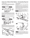
11. Tail Vise (Sold Separately)
a.
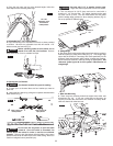
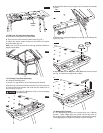
Locate the following parts:
(1) Clamp block (MDF), (2) Guide rods, (1) Threaded rod, (6)
Bolts and (6) Bolt covers.
b. Position clamp block (MDF) over guide rods, and threaded
r
od as shown in figure 16
c. Securely attach guide block to the rods with (6) washer and
bolts provided (Fig. 16).
d. Place one bolt cover over each screw head making sure it’s
flush to the table (Fig. 16).
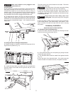
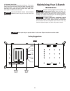
e. Locate the following parts:
(1) Threaded rod insert (2) Guide rod inserts, (3) Insert nuts, (2) Rod
blocks, (4) Screws, (4) Nuts and (1) Pin.
f. Insert rod inserts from the backside of frame completely into
the three holes provided (Fig. 17).
g. Secure rod inserts to frame with the three large nuts provided
from the front side of frame (Fig. 18).
Make sure the orientations of the mating nuts
are as indicated in the figures.
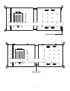
h. Place the rod block from backside of frame as shown, insert
two screws from the front side of frame into rod block and
secure with two nuts from backside of frame. Repeat this
procedure on other side of frame (Fig. 18).
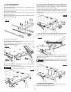
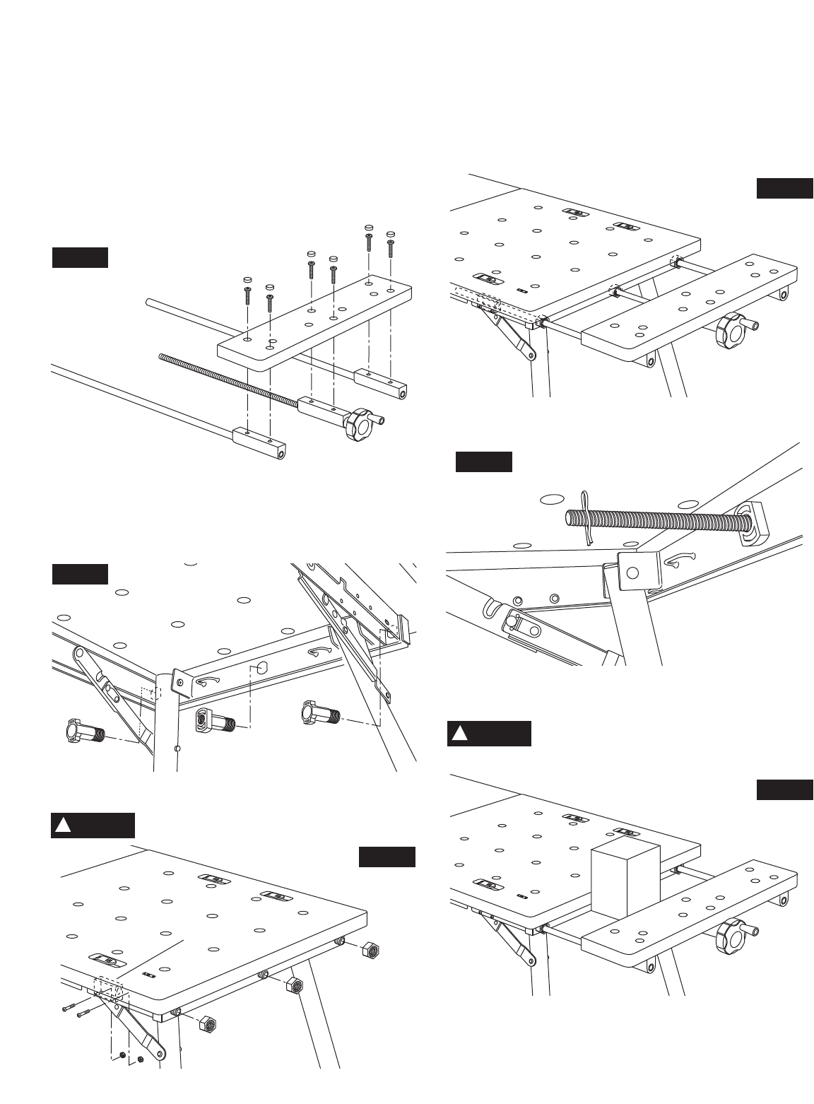
i. Insert guide rods and threaded rod into nuts and rod insert
making sure guide rods go thru rod blocks on each side of frame
while slowly threading rod with the knob into the frame like a
vise (Fig. 19).
j. Once the tail vise has been threaded into rod inserts, attach
the pin provided onto the end of the threaded rod (Fig. 20).
k. Place the selected object between the tail vise and table edge
and secure it by rotating the tail vise knob clockwise. Maximum
weight load is 40lbs.
When clamping small work pieces, the tail vise
only works when the work piece is in the middle
of the vise (Fig. 21).
12. Clamping Kit (Sold Separately)
a.
Dog hole clamps are placed in the dog holes to hold the work
pieces in place during cutting (Fig. 22).
8.
CAUTION
!
Fig. 16
Fig. 17
Fig. 18
F
ig. 19
Fig. 20
Fig. 21
CAUTION
!
Rod Block