


1514
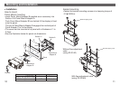
Mounting and Installation (continued)
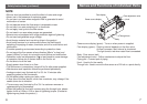
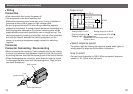
Wiring
Body of sensor
Lever
Cover (Option:ZS-33-F)
Lead wire connector
Connection
•
Make connection after turning the power off.
•Use a separate route when installing wire.
Malfunction stemming from noise may occur if wire is installed in
the same route as that of power or high-voltage cable.
•
Be sure to ground terminal FG when using a switching regulator
obtained on the market. If analog output is performed connecting to a
switching regulator obtained on the market, switching noise will be
superimposed and product specification can no longer be met. This
can be prevented by inserting a noise filter, such as a line noise filter
and a ferrite element, between the switching regulator and the
sensor
, or by using a seriespower supply instead of a switching
regulator.
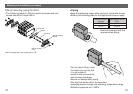
Connector
•
When connecting the connector, insert it straight onto the pin holding
the lever and connector body between fingers and lock the connector
by pushing the lever claw into the square groove in the body of
sensor
.
•When disconnecting the connector, push down the lever by thumb
to disengage the lever claw from the square groove. Then pull the
connector straight out.
Connector Connecting / Disconnecting
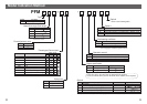
Brown DC(+)
Black OUT1
White
Select response time
Blue DC(
-
)
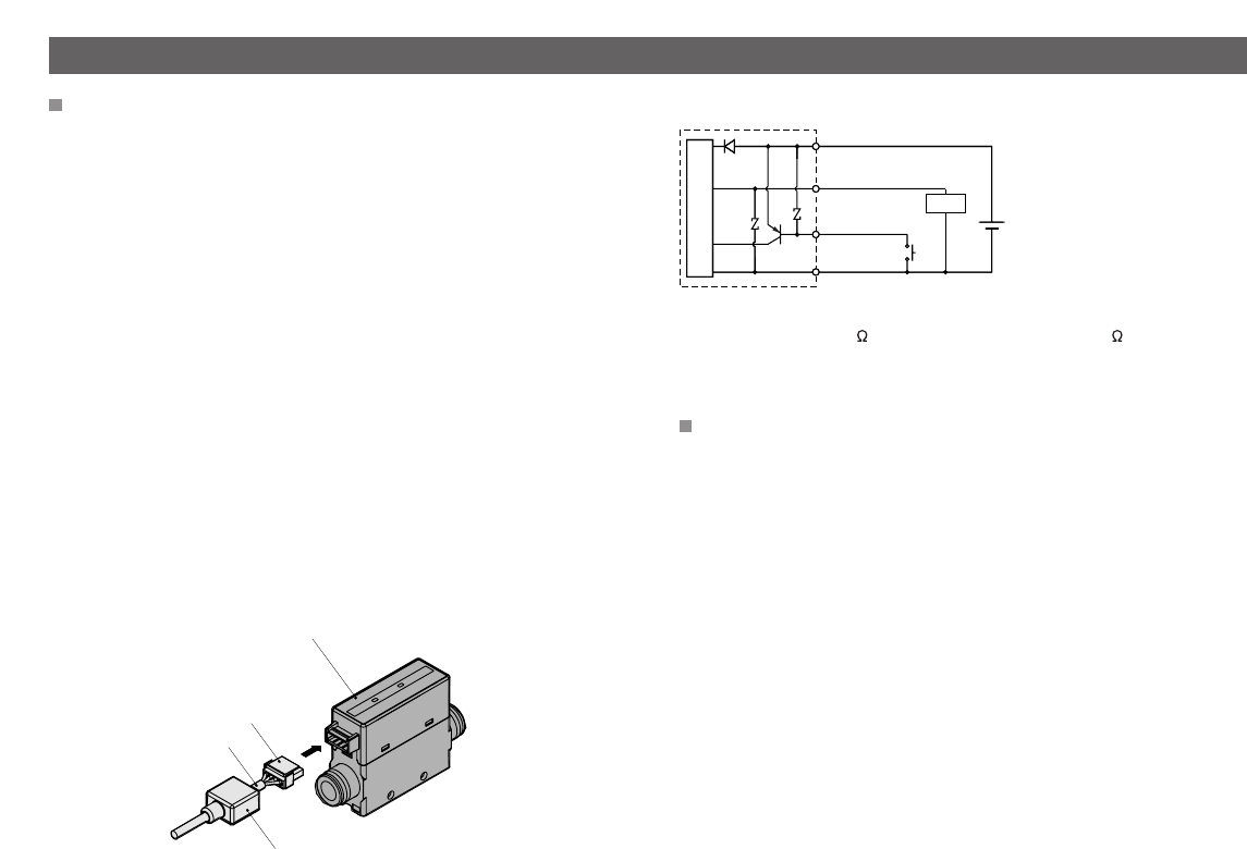
Main Circuit
DC24V
Analog output 1 to 5V
Output inpedance 1k
External input : No voltage input
Reed switch or solid state switch input
30ms or more
Load
Analog output 4 to 20mA
Load inpedance 50 to 600
Output circuit
Select response speed
•To reduce ripple by slowing the response speed when ripple of
analog output is large due to the effect of pulsation.
How to select
•Connect input line(white) to GND. While connected, response
speed is 1.0s. (50ms when not input)