


17
SERVICE
Good maintenance practice keeps the drill on the job and
increases its service life.
The most important maintenance practice is to keep the
hydraulic fl uid clean at all times. Contaminated hydraulic
fl uid causes rapid wear and/or failure of
internal parts.
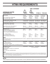
Follow the procedure contained in the HYDRAULIC SYS-
TEM REQUIREMENTS section of the manual to ensure
peak performance from the tool.
Never disassemble the tool unless proper troubleshooting
procedures have isolated the problem to an internal part.
Disassemble it only to the extent necessary to replace
the defective part. KEEP CONTAMINANTS SUCH AS
DIRT AND GRIT AWAY FROM INTERNAL PARTS AT ALL
TIMES.
Always determine and correct the cause of the problem
prior to assembly. Further wear and tool failure can result if
the original cause is not corrected.
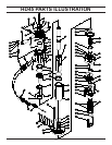
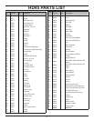
HAMMER DRILL DISASSEMBLY
PRIOR TO DISASSEMBLY
Clean exterior of tool.
Obtain Seal Kit (Part Number 05839). Replace all seals ex-
posed during disassembly. Note orientation of seals before
removing them. Install new seals in the same way.
DISASSEMBLY
1. Secure the drill in a bench vise with the “IN” and “OUT”
ports up, clamping on the fl ow sleeve tube between the
side rods. Soft vise jaws are recommended.
2. Remove the pigtail hose assemblies.
Note:
The drill is full of oil and will drip from the ports when the
hoses are removed.
3. Remove the charge valve cap from the top of the handle.
4. Remove the two capscrews (3/8 hex socket) and two
side rods. Remove handle assembly to expose ON/OFF
valve spool and accumulator diaphragm. Remove the mo-
tor assembly by tapping the top of the motor fl ange with a
plastic or rubber hammer.
5. Remove the accumulator valve block by tapping on its
underside with a plastic or rubber hammer. Tap on alter-
nate sides to ensure that the valve block comes off straight
without binding.
6. Remove piston from the fl ow sleeve assembly.
7. Remove the accumulator diaphragm and ON/OFF valve
from accumulator valve block, taking care not to damage
the valve stem. The valve, bushing and associated seals
will come out as an assembly. Turn the valve block upside
down to remove valve spring.
8. Clamp the accumulator valve body in a bench vise with
the IN/OUT ports facing up.
Do not overtighten the vise and distort the block.
9. Remove the porting block with a 3/8-16 thread slide
hammer or Tamper Sleeve Tool (part number 01120).
FLOW SLEEVE DISASSEMBLY
1. Remove the piston if not previously removed.
2. Place the fl ow sleeve assembly, automatic valve body
down, on Flow Sleeve Removal Tool (part number 04919),
which in turn is placed on Flow Sleeve Removal Tube (part
number 04910).
3. With an arbor press and using an aluminum disc to pro-
tect the fl ow sleeve, push on the fl ow sleeve to remove the
automatic valve body.
Use a rag in the bottom of the removal tube to protect
the automatic valve body when it drops out.
4. The automatic valve, four 1/4 x 1-1/2 inch push pins from
the fl ow sleeve and two 3/16 x 1-1/4 inch push pins from
the automatic valve body will come out.
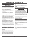
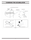
WARNING
Discharge accumulator.
IMPORTANT
IMPORTANT