


HG60 User Manual ◄ 11
PRE-OPERATION PROCEDURES
PREPARATION FOR INITIAL USE
Each unit as shipped has no special unpacking or as-
sembly requirements prior to usage. Inspection to as-
sure the unit was not damaged in shipping and does not
contain packing debris is all that is required. After instal-
lation of a grinding stone a unit may be put to use.
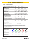
CHECK HYDRAULIC POWER SOURCE
1. Using a calibrated owmeter and pressure gauge,
check that the hydraulic power source develops a
ow of 7–10 gpm/26–38 lpm at 1500–2000 psi/105–
140 bar.
2. Make certain the hydraulic power source is equipped
with a relief valve set to open at 2200–2300 psi/152–
159 bar.
3. Check that the hydraulic circuit matches the tool for
open-center (OC) operation.
CHECK TOOL
1. Make sure all tool accessories are correctly installed.
Failure to install tool accessories properly can result
in damage to the tool or personal injury.
2. There should be no signs of leaks.
3. The tool should be clean, with all ttings and fasten-
ers tight.
CHECK TRIGGER MECHANISM
1. Check that the trigger operates smoothly and is free
to travel between the ON and OFF positions.
INSTALLING AND REMOVING GRINDING
STONES
READ AND BECOME FAMILIAR WITH THE SECTIONS
IN THIS MANUAL ON SAFETY PRECAUTIONS, TOOL
STICKERS AND TAGS, HYDRAULIC HOSE REQUIRE-
MENTS, HYDRAULIC REQUIREMENTS, AND PRE-
OPERATION PROCEDURES BEFORE USING THIS
PRODUCT.
NOTE:
Use 3 inch diameter up to 5 inch long (Type 16, 17, 18
or 19) grinding cones or plugs with a 5/8-11 threaded
arbor hole. Only use grinding cones or plugs which
comply with ANSI B7.1/ISO 525, 603.
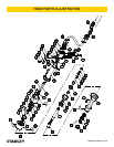
1. Install the abrasive cone or plug onto the spindle
(33). Using an open-end wrench on the ats of the
drive ange (51) and while griping the cone or plug,
tighten sufciently to prevent disengagement of the
cone or plug from the spindle.
CONNECT HOSES
1. Wipe all hose couplers with a clean lint-free cloth
before making connections.
2. Connect the hoses from the hydraulic power source
to the hose couplers on the grinder. It is a good prac-
tice to connect the return hose rst and disconnect
it last to minimize or avoid trapped pressure within
the grinder motor.
3. Observe ow indicators stamped on hose couplers
to be sure that oil will ow in the proper direction.
The female coupler is the inlet coupler.
NOTE:
The pressure increase in uncoupled hoses left in the
sun may result in making them difcult to connect.
When possible, connect the free ends of operating
hoses together.
OPERATING PROCEDURES
1. Observe all safety precautions.
2. Always start the grinder with the grinding stone
away from the work surface.
3. Move the hydraulic circuit control valve to the ON
position.
4. Squeeze the trigger momentarily. If the grinder does
not operate, the hoses might be reversed. Verify
correct connection of the hoses before continuing.
5. Start the grinder and move the grinding stone to the
work surface.
6. Grind a small amount of material at a time.
COLD WEATHER OPERATION
If the grinder is to be used during cold weather, preheat
the hydraulic uid at low engine speed. When using the
normally recommended uids, uid temperature should
be at or above 50 °F/10 °C (400 ssu/82 centistokes) be-
fore use.
OPERATION