


10 ► PG10 User Manual
PRE-OPERATION PROCEDURES
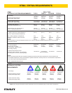
CHECK HYDRAULIC POWER SOURCE
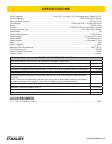
1. Using a calibrated ow meter and pressure gauge,
check that the hydraulic power source develops a
ow of 7–10 gpm/26–38 lpm at 2200–2300 psi/152–
159 bar.
2. Make certain the hydraulic power source is equipped
with a relief valve set to open at 2100–2250 psi/145–
155 bar minimum.
3. Check that the hydraulic circuit matches the tool for
open-center (OC) or closed-center (CC) operation.
CHECK TOOL
1. Make sure all tool accessories are correctly in-
stalled. Failure to install tool accessories properly
can result in damage to the tool or personal injury.
2. There should be no signs of leaks.
3. The tool should be clean, with all ttings and fasten-
ers tight.
CHECK TRIGGER MECHANISM
1. Check that the trigger operates smoothly and is free
to travel between the ON and OFF positions.
CHECK GUARD WELDMENT
1. Inspect the wheel guard weldment for cracks and
other structural damage.
INSTALLING AND REMOVING
GRINDING WHEEL
NOTE:
Use 6 inch diameter up to 3 inch thick (Type 6 for
USA) grinding wheels with a 5/8-11 threaded arbor
hole. Only use grinding wheels which comply with
ANSI B7.1, B7.5/ISO 525, 603.
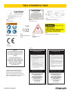
READ AND BECOME FAMILIAR WITH THE SECTIONS
IN THIS MANUAL ON SAFETY PRECAUTIONS, TOOL
STICKERS AND TAGS, HYDRAULIC HOSE REQUIRE-
MENTS, HYDRAULIC REQUIREMENTS, AND PRE-
OPERATION PROCEDURES BEFORE USING THIS
PRODUCT.
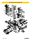
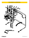
1. Unscrew the two nuts (98) which secure the guard
weldment (95) to the frame and remove the guard
weldment.
2. Install the grinding wheel until it comes in contact
with the drive ange.
3. Using the wrench (89) provided, place it on the
ats of the drive ange. Place a strap wrench on
the grinding wheel and then tighten by gripping and
turning the strap wrench while holding the wrench
provided.
4. Replace the guard weldment.
IMPORTANT
Never over-tighten the grinding wheel by impacting
the wrench with a mallet or hammer. Sufcient
torque is attained by hand-tightening the wheel with
a strap wrench while securing the drive ange with
the wrench provided.
ADJUST WHEEL FLANGES TO FIT RAIL
The wheel anges may be adjusted to t the width of the
rail by removing one or more of the washers.
CONNECTING THE HOSES
1. Wipe all hose couplers with a clean lint-free cloth
before making connections.
2. Connect the hoses from the hydraulic power source
to the hose couplers on the grinder. It is a good prac-
tice to connect the return hose rst and disconnect
it last to minimize or avoid trapped pressure within
the grinder motor.
3. Observe ow indicators stamped on hose couplers
to be sure that oil will ow in the proper direction.
The female coupler is the inlet coupler.
NOTE:
The pressure increase in uncoupled hoses left in the
sun may result in making them difcult to connect.
When possible, connect the free ends of operating
hoses together.
OPERATION