


10 ► RD12 User Manual
OPERATION
PREOPERATION PROCEDURES
PREPARATION FOR INITIAL USE
The tool as shipped has no special unpacking or assem-
bly requirements prior to usage. Inspection to assure the
tool was not damaged in shipping and that it does not
contain packing debris is all that is required. Otherwise,
the tool may be connected to a hydraulic source upon
receipt.
CHECK HYDRAULIC POWER SOURCE
1. Using a calibrated owmeter and pressure gauge,
check that the hydraulic power source develops a
ow of 8–10 gpm/30–38 lpm at 2000 psi/140 bar.
2. Make certain the hydraulic power source is equipped
with a relief valve set to open at 2200–2300 psi/152–
159 bar ma×imum.
3. Make certain that the power source return pressure
does not e×ceed 250 psi/17 bar.
CONNECT HOSES
1. Wipe all hose couplers with a clean lint-free cloth
before making connections.
2. Connect the hoses from the hydraulic power source
to the hose couplers on the tool. It is a good prac-
tice to connect the return hose rst and disconnect
it last to minimize or avoid trapped pressure within
the tool.
3. Observe ow indicators stamped on hose couplers
to be sure that oil will ow in the proper direction.
The female coupler is the inlet coupler.
4. Observe the IN and OUT port lettering on the valve
block assembly to ensure that the hydraulic ow is in
the proper direction. The IN port lettering indicates
the inlet (pressure) side.
NOTE:
The pressure increase in uncoupled hoses left in the
sun may result in making them difcult to connect.
When possible, connect the free ends of operating
hoses together.
USING COOLANT
The RD12 rail drill is equipped with a separate coolant
can assembly that is used to deliver coolant to the drill
bit. Follow the instructions below to use the coolant can
assembly with the rail drill:
1. If operating the rail drill at temperatures above
32 °F/0 °C, ll the coolant can with ordinary tap wa-
ter.
2. If operating the rail drill at temperatures below
32 °F/0 °C, ll the coolant can with a mi×ture of 50%
ordinary tap water and 50% biodegradable anti-
freeze.
3. Pressurize the coolant can using the carrying han-
dle/pump.
4. Connect the coolant can assembly to the rail drill us-
ing the supplied quick-disconnect coupler.
OPERATING PROCEDURES
1. Observe all safety precautions.
2. Make sure the drill bit you intend to use contains
carbide inserts with good cutting surfaces. If the
surfaces are worn or chipped, unscrew the retaining
screw and rotate the insert to a good cutting surface.
If the inserts do not contain a good cutting surface
on one of the four sides, replace the inserts. Make
sure the bit holder is not damaged.
3. Install the drill bit into the piston machining assem-
bly (24) and then turn it clockwise until it stops.
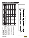
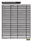
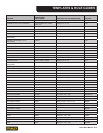
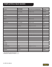
RAIL TEMPLATES & HOLE GUIDES
NOTE:
The RD12 must be used with rail templates and hole
guides. See the chart at the end of this section for
selections of rail templates and hole guides.
1. Install a hole guide assembly onto the rail and posi-
tion it where you want to drill.
2. Install templates onto the rail drill with the rail size
facing the rail.
NOTE:
To avoid drill bit damage, make sure the drill bit/pis-
ton assembly is fully retracted prior to placing the
RD12 on the rail.
3. Set the rail drill over the hole guide on the rail so that
the templates are nested between the ball and the
base of the rail and the adjustment screw (52) ts in
a slot in the hole guide.
4. Adjust the threaded shaft (44) until there is no move-
ment of the rail drill as it sits on the rail and the hole
guide. Wiggle the RD12 to remove all looseness.
Then lift the handle (49) up and turn the threaded
shaft (44) clockwise appro×imately 1/2 turn. Push
the handle (49) down hard to rmly clamp the RD12
to the rail.