


10 ► SK58 User Manual
NOTE:
If uncoupled hoses are left in the sun, pressure in-
crease within the hoses may make them difcult to
connect. When possible, connect the free ends of
the hoses together.
5. Connect the hose from the air supply to the hose on
the tool.
NOTICE
The air supply must be minimum 30 cfm at 120
psi. Supplying less than these specications may
result in inadequate extraction of rock cuttings;
cause cuttings to migrate up the drill steel and
into the tool and result in tool damage; diminish
drilling time; and cause premature wear of the
drill bit.
OPERATION PROCEDURES
1. Observe all safety precautions.
2. Install the appropriate tool bit for the job.
3. Start the hydraulic supply and turn the circuit control
valve to the ON position.
4. Open the air valve on the tool just enough to permit
a small amount of air ow from the tool bit.
NOTE:
Air ow must be continuous during drilling to avoid
clogging of the air passages and/or back-ushing of
waste products into the drill.
5. Place the bit rmly on the surface to be drilled.
6. Open the hydraulic valve lever slightly to start the
tool at a slow speed. Adequate down pressure is
very important.
7. Ensure the rock bit is rotating at a moderate speed
(not too fast, not too slow). When starting the hole,
it is best to start at a slow impact and rotation speed
until the rock bit has carved out a depression in the
material being drilled. If the rock bit is not rotating
open the hydraulic valve lever further. If the rock bit
still does not rotate adjust the motor control knob
until rotation is achieved.
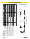
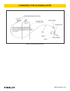
The recommended hose size is .500 inch/12 mm I.D. up
to 50 ft/15 m long and .625 inch/16 mm I.D. minimum up
to 100 ft/30 m.
PRE-OPERATION PROCEDURES
CHECK POWER SOURCE
1. Using a calibrated owmeter and pressure gauge,
check that the hydraulic power source develops a
ow of 7-9 gpm/26-34 lpm at 1500-2000 psi/105-
140 bar.
2. Make certain the hydraulic power source is equipped
with a relief valve set to open at 2100-2250 psi/145-
155 bar maximum.
INSTALL DRILL STEEL & ROCK BIT
Use standard 4-1/4 inch shank × 1 inch hex drill steel
for SK58110, SK58120 and SK58310 models and 4-1/4
inch shank × 7/8 inch hex drill steel for the SK58130
model.
Drill steels are available in a variety of lengths. Start
with a short length so that the tool may be operated at a
normal standing position. The tool handles should never
exceed chest height during operation.
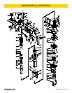
1. Thread a rock bit onto the drill steel.
2. Rotate the latch (61) out and up.
3. Slide the drill steel into the tool.
4. Rotate the latch down being careful not to pinch your
ngers. When correctly installed, the collar on the
drill steel should be above the bottom of the latch.
CONNECT HOSES
1. Wipe all hose couplers with a clean, lint-free cloth
before making connections.
2. Connect the hoses from the hydraulic power source
to the tool ttings or quick disconnects. It is a good
practice to connect return hoses rst and discon-
nect them last to minimize or avoid trapped pressure
within the tool.
3. Observe ow indicators stamped on hose couplers
to ensure that uid ow is in the proper direction.
The female coupler on the tool hose is the inlet cou-
pler.
4. Move the hydraulic circuit control valve to the ON
position to operate the tool.
OPERATION