


-6-
BASIC TOOL OPERATION
MAINTAINING THE PNEUMATIC TOOL
When working on air tools, note the warnings in this manual and use extra care
evaluating problem tools.
CAUTION:
Pusher spring (constant force spring). Caution must be used when working with the spring
assembly. The spring is wrapped around, but not attached to, a roller. If the spring is extended
beyond its length, the end will come off the roller and the spring will roll up with a snap, with a
chance of pinching your hand. Also the edges of the spring are very thin and could cut. Care
must also be taken to insure no permanent kinks are put in the spring as this will reduce the
springs force.
REPLACEMENT PARTS:
STANLEY-BOSTITCH replacement parts are recommended. Do not use modified parts or parts which will not
give equivalent performance to the original equipment.
ASSEMBLY PROCEDURE FOR SEALS:
When repairing a tool, make sure the internal parts are clean and lubricated. Use Parker “O”-LUBE or
equivalent on all “O”-rings. Coat each “O”-ring with “O”-LUBE before assembling. Use a small amount of oil on
all moving surfaces and pivots. After reassembly add a few drops of STANLEY-BOSTITCH Air Tool Lubricant
through the air line fitting before testing.
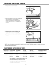
AIR SUPPLY-PRESSURE AND VOLUME:
Air volume is as important as air pressure. The air volume supplied to the tool may be inadequate because of
undersize fittings and hoses, or from the effects of dirt and water in the system. Restricted air flow will prevent
the tool from receiving an adequate volume of air, even though the pressure reading is high. The results will be
slow operation, misfeeds or reduced driving power. Before evaluating tool problems for these symptoms, trace
the air supply from the tool to the supply source for restrictive connectors, swivel fittings, low points containing
water and anything else that would prevent full volume flow of air to the tool.
WARNING:
!
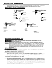
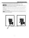
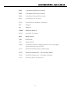
Stanley-Bostitch pneumatic tools are cycled by a compressed air operated single piston design. The following
illustrations show the four functional cycles that occur when the tool is operated to drive a fastener:
BASIC SINGLE PISTON STAPLER/NAILER
FIG.1
AT REST
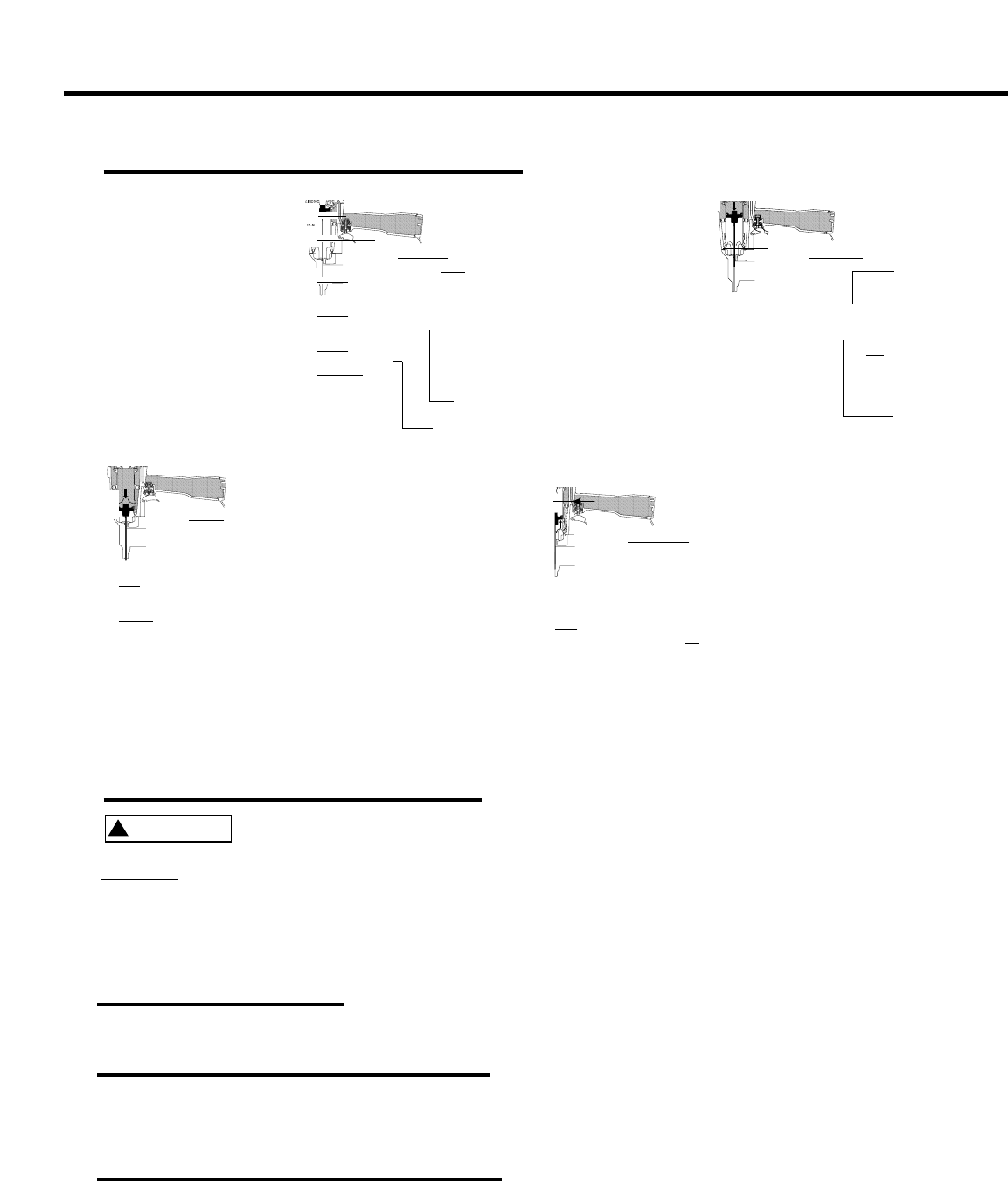
FIG.2
DRIVING STROKE
FIG.3
END OF STROKE
TRIGGER STILL
PULLED
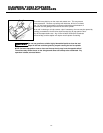
FIG.4
RETURNING
HEAD VALVE CLOSED
EXHAUST
OPEN
AIR IN
RETURN
CHAMBER
PUSHES
PISTON
UPWARD
EXHAUST
STILL
CLOSED
HEAD VALVE OPEN
TRIGGER VALVE
STILLACTUATED
AIR FLOWS
INTO
RETURN
CHAMBER
PISTON IS
SEALED
AGAINST
BUMPER
TRIGGER VALVE
RELEASED –
AIR PRESSURE RETURNS
TO TOP OF HEAD VALVE
EXHAUST
SEALED BY
PISTON STOP
HEAD VALVE OPEN
TRIGGER VALVE PORT
BLOCKED
AIR RELEASED
FROM ABOVE
HEAD VALVE
TRIGGER VALVE
ACTUATED
EXHAUST
OPEN
HEAD VALVE CLOSED
SLOTS FOR AIR FLOW
FOR PISTON RETURN
TRIGGER VALVE RELEASED
PASSAGE FOR
AIR RELEASED FROM HEAD VALVE
TRIGGER VALVE PORT
(TO SUPPLY AIR TO TOP OF HEAD VALVE)
PISTON
STOP
RETURN
CHAMBER
BUMPER
RESERVOIR
OF HIGH
PRESSURE
AIR
HOLES IN
CYLINDER
WALL
RESERVOIR OF
HIGH PRESSURE AIR