


Safety Instructions
General Precautions
Precautions against Gas Explosions
Precautions when Handling Batteries
The output marked “domestic battery” comprises an intelligent,
software-controlled boost function which charges the domestic
Before connecting and running your Sterling alternator-to-
battery bank up to five times faster and much more efficient than a
battery charger, read the complete instructions and all
standard alternator could do. In addition, the batteries will take in up
cautionary labels on the unit and on the batteries. Only a
to 50% more charge current, allowing you to utilise their full capacity.
correct installation according to these instructions will let
While the alternator-to-battery charger greatly improves the charging
you take full advantage of your alternator-to-battery
of the domestic battery bank, the starter battery has always priority,
charger.
ensuring that the engine can be started at any time. Under no
circumstances will the system allow the starter battery to drop below
13V.
Always install the unit in a dry, cool and well-ventilated place.
Additional functions protect your electrical system and your batteries
Any contact with water and heavy humidity has to be avoided.
from possible faults such as overcharging or overtemperature. Any
Do not cover the fans to prevent the unit from overheating.
fault on the system will be indicated by a number of LEDs or on the
optional remote control unit.
Make sure all cables have the appropriate size and are in good
condition. Do not run the unit with cables that are damaged or
How it works
otherwise inappropriate.
In order to maximise the alternator output current, the alternator-to-
battery charger pulls the alternator output voltage down to about
13V. Then this low voltage is amplified to a higher voltage suitable
The alternator-to-battery charger contains electrical
for effective battery charging, i.e. 14.1V to 14.8V. The unit’s
components which may produce sparks. In order to avoid the
intelligent software automatically calculates the optimum charge
risk of fire or explosion, do not install the unit in rooms
cycle and absorption time. When the batteries have been fully
containing batteries or highly inflammable materials or in any
charged, the voltage is reduced to float voltage (appr. 13.5V to
place requiring explosion-proof equipment. This includes any
13.8V).
room with petrol, gas or diesel driven engines or with tanks or
piping used for any such substance.
Before starting to install the charger please ensure that there is
Product Characteristics
sufficient ventilation. In order to prevent the formation of
explosive gases make sure that the batteries have not been
Easy installation: It could not be easier. For the basic system only
charged for at least 4 hours prior to installation.
4 connections are required: one from the alternator(s), one to each
battery bank and one to the common negative. Apart from the
additional negative connection most of these cables will be on board
anyway.
Someone should be within earshot, i.e. close enough to come
to your aid when working near a lead-acid battery. Have plenty
Advanced charging technology: Intelligent, software-controlled,
of water and soap nearby in case battery acid comes in
4step charging of the domestic battery including temperature
contact with skin, clothes or eyes. Wear complete eye
compensation.
protection and protective clothing. Avoid touching the eyes
No interference with engine electronics: Because the system
while working with a battery.
does not increase the voltage of the starter battery there is no risk of
If battery acid contacts skin or clothing, wash immediately with
problems with the electronic engine management system.
soap and water. If acid enters the eye(s), flood eye(s) with
No work on the alternator required: Absolutely no changes to the
running cold water for at least 10 minutes and seek medical
alternator are required. As a result no warranty conflicts can arise.
attention immediately.
Never smoke or allow a spark or flame in the vicinity of a
Suitable for multiple alternators: Unlike other systems the
battery or the engine.
alternator-to-battery charger can be used simultaneously on more
than one alternator, saving even more installation work and money.
Work with extra caution to reduce the risk of dropping a metal
tool onto a battery. It may create sparks or short-circuit the
Starter battery priority: The system ensures that the starter battery
battery or other electrical parts that may cause an explosion.
is always kept in operational condition.
Remove all personal metal items such as rings, bracelets,
Intelligent fault protection: The unit comprises multiple safety
necklaces, watches and jewellery when working near a battery.
features and fault indicators. Even in the unlikely event of a
A battery can produce a short-circuit current high enough to
complete failure, the unit will still work as a split charge diode.
weld a ring or any other metal which will lead to serious burns.
Enhanced installation options: The unit comes with temperature
Never charge a frozen battery.
sensors for the battery and the alternator. It can be enhanced by an
optional remote control.
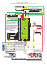
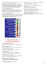
General Overview
Basic Installation
The Sterling alternator-to-battery charger is a fully automatic,
electronic multi-stage split-charge system which charges two
banks of batteries from one or more alternators. It combines an
advanced split charge diode system with a powerful voltage
amplifier. The unit has one input to connect to one or more
alternators and two outputs to charge two different battery
banks.
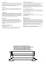
Install the unit in a cool and well-ventilated position close to the
The output marked “starter battery” is a straight channel
alternator(s). Also, the installation point has to be dry and free from
through a diode; this is the channel that is connected to the
heavy condensation since the unit is not waterproof. Do not fit it in a
boat / vehicle engine system. In order to avoid any conflicts
closed box as this might lead to overheating of the unit and reduced
with an electronic engine management system, there is no
performance.
boost function on this channel.
The unit has three temperature-controlled fans. Therefore they will
Important: These guidelines refer to the connections that have
to be made for the correct installation of the Sterling Alternator-
to-Battery Charger. On an existing system you may also be
required to remove some of the connections that were used to
charge the batteries prior to the installation of the unit.
run more often when the unit is installed in a place with a high first two seconds of having the ignition key fully turned. During
ambient temperature. these two seconds, a 12 volt feed is sent to the alternator B+
terminal which is enough to let the alternator fire up. Thereafter,
Before connecting the unit to your alternator(s) make sure that
the alternator looks after itself. Use a 0.5mm² wire for this
your alternator-to-battery charger ist rated for the maximum
connection.
output of the alternator(s).
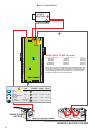
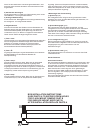
Connect the main alternator output(s) (B+) to the centre stud
Multiple Alternators: The alternator-to-battery charger can be
marked “ALTERNATOR INPUT. Then simply connect the other
used on more than one alternator at the same time. Simply
studs to the engine battery and to the domestic battery,
connect all alternator outputs (B+) to the alternator input terminal
respectively. Make sure that the cables used can carry the full
on the unit. Make sure that your alternator-to-battery charger is
current of the alternator(s). Choose a cable size that can carry at
rated for the combined maximum output of the alternators.
least twice as much current than required. For example, if you
have a 70A alternator, then use a 140A cable.
Remote Control: The remote control kit is an optional extra
If you are only going to charge one bank of batteries, then use the
including a remote display and two 200A shunts. The two shunts
“DOMESTIC BATTERY” output only. The “START BATTERY”
measure the current coming from the alternator and the
output can remain unused without affecting the performance of
current going into the starter battery . From these values the
the unit.
electronics will calculate the current going into the domestic
battery.
The unit has a short negative wire which has to be extended and
connected directly to the alternator negative (or case) using a 60A
The remote control will keep you informed about voltages,
cable.
currents, temperatures and other operating figures. In the event
If you currently have a split charge diode, then the three positive of a problem, it indicates what the problem is.
wires are already there. Simply replace the split charge diode with
the alternator-to-battery charger and connect the negative wire to
the alternator.
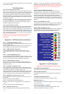
Battery Type Selection
Important: If your alternator has got its own battery voltage sense
Programme the type of your domestic battery into the unit by
wire, then this has to be removed from the battery terminal and
using the dip switches . The unit has four different battery type
should be connected to the alternator’s own B+ output instead.
settings:
This will prevent contradictory regulation between the alternator
Non-sealed lead-acid batteries (where you can unscrew the lid
and the alternator-to-battery charger.
of the battery and top it up with water): The absorption voltage is
14.8V.
Extended Installation
For additional functions and improved performance some extra
features can be installed. Note that this extended installation is
Gel batteries (Exide specification): This is the new
optional and is not required for the unit to work.
specification for gel batteries as laid down by Exide. The
absorption voltage is 14.4V.
Battery Temperature: Using its ring terminal end, connect
one of the enclosed temperature sensors to your domestic
Gel batteries (U.S. specification): This is the standard U.S.
battery’s negative post.
specification for gel batteries. The absorption voltage is 14.1V.
Connect the two small wires on the other end
to the small terminals marked “battery temp”. Be careful not to
Sealed lead-acid batteries and AGM batteries: These batteries
damage or alter the temperature sensor in any way! The system
are also charged at an absorption voltage of 14.4V, however with
will then sense the battery temperature and change the output
a shorter absorption time.
voltage in accordance with the recommended temperature
compensation for the selected battery type.
The ideal absorption time for each battery type is recalculated
automatically for each new charging cycle.
Important: All voltages indicated in these instructions refer to an
ambient temperature of 20°C. When using a battery temperature
sensor these voltages will be different due to temperature
Start-Up and Test Procedure
compensation.
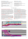
As soon as the unit is connected, it senses the output voltage
Alternator Temperature: Using its ring terminal end,
from the alternator. When the alternator is producing voltage, the
connect one of the enclosed temperature sensors to your
alternator-to-battery charger will start up, indicated by a slow
alternator case or negative stud.
flashing of the top green LED. The start-up phase will be about 2
Connect the two small wires on the other
to 3 minutes during which the unit is only working as a passive
end to the small terminals marked “alt temp”. Be careful not to
split charge device.
damage or alter the temperature sensor in any way! The system
When the start-up phase is completed, the top green LED (1) will
will then sense the alternator temperature and will disengage the
come on constantly, indicating that the unit is now in the constant
voltage amplifier if the alternator temperature exceeds 100°C.
current phase and is boosting the current into the domestic
battery bank. At the same time, the load on the alternator will
Voltage Sensing: The alternator-to-battery charger in its
increase.
standard configuration senses all voltages directly at the unit.
However, in order to compensate a possible voltage drop
The voltage on the domestic battery output will then rise until it
between the unit and your domestic battery, you can run a simple
reaches the absorption voltage for the selected battery type.
0.5mm² wire from the positive stud of your domestic battery to the
After that the output will be kept constant on absorption voltage
terminal marked “dom sense”.
(14.1V to 14.8V) and the yellow timer LED (2) will come on. The
unit’s intelligent software automatically calculates the optimum
Starter solenoid: Some alternators will not fire up without a
absorption time (between 1 and 24 hours.)
voltage on their B+ terminal. Because the alternator-to-battery
When the batteries are fully charged, the voltage will be reduced
charger contains a split charge diode there will be no voltage feed
to a constant float voltage (13.6V to 13.8V).
on the B+ terminal which means that the engine will start but the
During the boost and the absorption phase the entire charging
alternator may not work. If this is the case, then you need to use
cycle is suspended for 3 minutes every 20 minutes to provide
the starter solenoid feed terminal on the alternator-to-battery
additional charge capacity for the starter battery.
charger. It connects to the starter motor terminal which only
becomes live when the starter motor bendix is engaged, i.e. the
If, thereafter, the voltage of the domestic battery drops below
(5)
(9)
(8)
(6)
(1)
(10)
(3)
(4)
Important: Fast charging costs water! Check the water level in
your batteries regularly and top-up if necessary. Do not overfill!
Do not use any positive battery terminal
for this connection!
Do not use any positive terminal
(B+) for this connection!
ALTERNATOR-TO-BATTERY CHARGER
INSTRUCTIONS
2 3