


STUDER INNOTEC
XP-COMPACT
the transfer contact is active, then you have at the output AC OUT the same voltage as that at the
input. This voltage can not be modified by the XP-COMPACT!
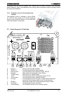
4.8.1 Set the transfer voltage threshold
The voltage threshold of the transfer is factory settled at 200Vac. This value is acceptable in most
application. However, this value can be adjusted fro 150 to 230Vac if necessary. To proceed to the
adjustment of this level, insert a screw-driver N° 0 vertically in the hole (23) and turn gently clock-
wise or counter clockwise to increase or diminish the threshold level.. When the Input voltages
reach the settled value on turning knob, the inverter switch off and the AC INPUT go directly on the
AC OUTPUT. When the voltage INPUT is less of 20V the value set, the transfer is stop and the
OUTPUT switch back on the inverter.
Don’t use the turning knobs “TRANSFERT” (23) to adjust the AC OUTPUT voltage!
This is only it’s only a voltage threshold level to enable or disable the transfer.
4.8.2 FAST (UPS)- MODE for the Transfer Switch
The quick and break free Transfer mode is programmed with a slide switch „Transfer Delay“ OFF,
which is on the front side (cable connections side).
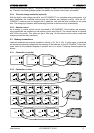
The aim of the XP-COMPACT is to supply the consuming appliance with a break-free alternating
voltage. When the incoming voltage AC IN no longer matches values which have been set with the
Turning Knob 23, the Inverter switches on at once. The transfer is carried out in 0.02 seconds. This
quick transfer ensures a break-free function for most consuming appliances. If you have an alter-
nating voltage back at the input AC IN, transfer system starts up again without any break, and the
inverter is stopped.
4.8.3 Delayed mode of the Transfer System
The delayed mode of the transfer system „Transfer Delay ON“ is programmed with the slide switch
on front with the cable connections. The XP-COMPACT provides a break-free alternating voltage
for the consuming appliance. A quick transfer switch is not always sensible nor is it always desired.
For example, when the consuming appliances are operated by a small back-up generator, an over-
load of a short duration on such a generator, i.e. start of a vacuum cleaner etc., has the effect of
decreasing the voltage for a short time. As in such cases the transfer to the Inverter is not desir-
able, the transfer system can be programmed with a delay. When the slide switch (Transfer delay)
is in the „On“ position, the transfer to the inverter takes place with a delay of 5 seconds. If the volt-
age falls below 100Vac, the transfer takes place without delay! The transfer switching to the In-
verter takes place without any break.
4.9 The Solar charge controller (option)
The XP-COMPACT also has a Solar Charge Controller built in. For charging the batteries, Solar
modules can be connected to the screw terminal SOLAR +/-. The in-built controller is a „Shunt con-
troller“ for the maximum input current of 30A for XPC 1112 and XPC 1624 and 20A for XPC 1648.
The operating voltage of Solar panels to be connected must match the actual operating voltage of
the XP-COMPACT and never exceeds the max. rated value.
Under no circumstances should any other systems such as wind-generator be connected at the
input of the Solar Charge Controller.
The Solar Charge Controller works automatically and is always in operation. As soon as the energy
is delivered from the Solar Charge Controller, LED 3 “SOLAR CHARGE” is lit and the batteries are
being charged. The Solar Charge Controller works even when the Battery Charger is functioning.
The way of working is the principally the same as that of the Battery Charger. The function is de-
scribed in the section on Battery Charger. The programming and the adjustments, thanks the op-
tional remote control, are carried out in accordance with the same conditions. Check with your bat-
tery supplier which adjustments must be carried out for your battery.
User manual XP-COMPACT V2.0 E
15