


STUDER Innotec
XP-COMPACT
User manual XP-COMPACT V5.1 E 11
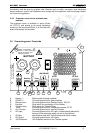
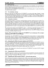
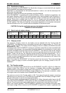
4.2 Display and control parameters on remote control panel (optional)
160
OFF
AC OUT
Over Temp.
Overload
AC IN
SOLAR CHARGE
Contact manual
Contact active
Program
COMPACT
AUXILIARY CONTACT
ON/OFF
INVERTER - CHARGER
(Select)
RCC-01
INVERTERCHARGER
(Program) (Change status)
Battery
Low/High
RESET
ALARM
10
20
30
40
50
60
70
80
90
100
TRANSFER
Charger
Inverter
5
10
20
40
60
80
100
130
160
A %
EQUALIZE
1
15
16
17
18
19
2
3
21
4
5
6 13
12
11
10
20
25
8
7
9
14
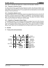
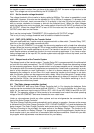
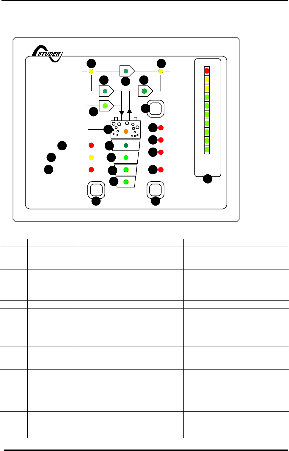
4.3 Light Emitting Diodes (LED)
LED Marking LED lit LED blinks
1 AC IN Voltage at the AC IN input is within
the accepted range (voltage and
frequency)
Voltage, outside of the self-
adjusted values is at the AC IN
input.
2* CHARGER Battery Charger is working The input voltage is out value
(voltage or frequency)
3 SOLAR
CHARGE
Connected Solar modules are
delivering energy
4* Program Program mode for Aux. Contact
5* Contact active Auxiliary Contact is activated
6* Contact manual Aux. Cont. manually activated
7 Transfer system is active. Input
AC voltage is directly connected to
AC OUT outlet
Transfer system (by-pass) is dis-
abled (see chap.6.5.1)
8 AC OUT Voltage is present at the AC OUT
outlet
The Inverter is in Standby mode.
No loads are detected at the out-
put
9* INVERTER Inverter is working Inverter mode is disabled (see
chap.6.5.1)
10* Over Temp. For the time being the XP-
COMPACT is out of service be-
cause of overheating.
11* Overload The XP-COMPACT is out of ser-
vice because of overload or short-
circuit
Overload due to connection of the
grid or the generator at the output
of the inverter. Please Check the