


STUDER Innotec
XP-COMPACT
User manual XP-COMPACT V5.1 E 20
6.4.3 Example
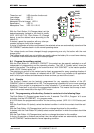
6.4.3.1 Auxiliary Contact as generator starter
When in the programming of the Auxiliary Contact, the Battery Capacity (LED 15-18) is used as a
condition, then you must take note of the following requirements.
If you have to start an emergency back-up supply with a battery having a certain residual capacity,
then two battery levels must be programmed. The first (i.e. Battery 25% LED 17) for starting or
activating the Auxiliary Contact, and the second (i.e. Battery 100% LED 15) for stopping or deacti-
vating the Auxiliary Contact. By programming like this the Auxiliary Contact is active with the lowest
set condition and release when it has reached the highest programmed condition through charging.
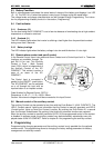
6.4.3.2 Auxiliary Contact as Twilight Switch (With solar charger option)
The Auxiliary Contact of the XP-COMPACT can also be used as a twilight switch, i.e. for operating
automatically the exterior lighting. With it the connected solar modules measure the light intensity.
To function as a twilight-switch the Auxiliary Contact must be programmed so that the condition
SOLAR CHARGE (LED 3) is active. Programming must be carried out in steps and in accordance
with the description for the programming of the Auxiliary Contact.
6.4.3.3 Second priority cut-off
The Auxiliary Contact can use to cut-off second priority load with the criteria of the battery status or
overtemp. One of the 4 LED 15 to 18 or 10 will be chosen as the cut off criteria. The second prior-
ity loads will be supply only if the battery as a sufficient residual capacity
6.5 Disabling some of the XP-COMPACT functions
Each different function charger, inverter and transfer can be disabled. This is useful for specific
applications witch required to disable some of these tree functions.
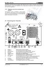
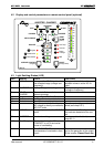
If you press the buttons (19 and 20) more than 2 seconds, you can have the access to the different
possibilities shown in the following diagram.
In programming mode the display show only the different types of program with the three DEL 2,7
and 9 to each functions. To change the type of programming press shortly the button 20 until your
reach to the right function use according table below. After 10 seconds the XP-COMPACT exits the
programming mode and load the new change.
In user mode, the disabled functions are displayed by blinking LED. So you can see in witch mode
is disabled.
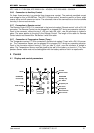
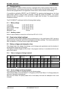
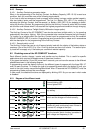
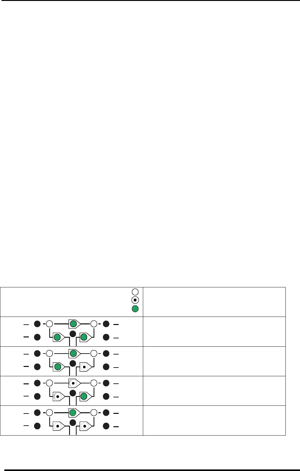
6.5.1 Diagram of the different mode
9
Show an off LED
Show a blinking LED
Show a lighted LED
CHARGER
INVERTER
AC OUTAC IN
1
2
7
8
9
All the functions are enabled. This is the fac-
tory setting.
CHARGER
INVERTER
AC OUTAC IN
1
2
7
8
9
The inverter is disabled. Only the transfer
switch and the charger will work normally.
CHARGER
INVERTER
AC OUTAC IN
1
2
7
8
9
Charger and transfer switch are disabled. the
inverter will work continuously even if there is
a correct AC voltage at the input
CHARGER
INVERTER
AC OUTAC IN
1
2
7
8
9
Inverter and charger are both disabled.
Only the transfer switch function is enabled in
input voltage and frequency is OK.