


Steca Xtender
Installation and Operating Instructions 723.932 Xtender V0.511 Seite 21
If the BTS-01 temperature sensor is used, the voltage adjustment thresholds for the battery are
corrected in real time by means of the battery temperature. The value of this correction is set by
the configuration {1139} in the configuration table p. 35.
Much more complex charge profiles or exclusion of the charger can be configured using
the RCC-02/03 remote control.
Configuration of the battery is the responsibility of the operator. Incorrect configuration
that does not correspond to the charging methods of the battery recommended by the
manufacturer may be dangerous and/or considerably diminish the battery service life. If
the factory settings are modified, it is imperative that the new values be entered in the
configuration table p. 35
6.2.6
L
IMITING THE INPUT CURRENT BY LIMITING THE CHARGER CURRENT
In order to best use the resources available at the input (depending on the generator size or the
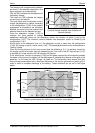
grid output) the Xtender has a system known as power sharing.
This is a system that allows the current of the charger to be limited – from its target value {1138}
to 0 – according to the current used at the output in relation to the maximum current available at
the input set by the configuration {1107}. The greater the current at the output, the more the part
of the current at the input assigned to charging the battery is reduced. If the current exceeds the
limit, the transfer relay will be open and the consumers therefore supplied exclusively by the
inverter, as long a the output current exceeds the limit of the input current. Exceeding the limit
value may be authorised by the configuration of {1436}.
This system allows the sharing of power available by giving priority to the AC output (AC out) and
to the consumers who are connected to it. The charger will only use the power not utilised at the
output to ensure that the battery is charged. Once the charge current decreases by going into
“power sharing” mode, the indicator (45) flashes.
The limit value of the input current is set by the configuration {1107} and may be adjusted via the
RCC-02/03 remote control.
In the case of mobile applications the installation of an RCC-02/03 remote control is
recommended, in order to be able to adapt the value of the input current limit if
necessary, for each connection to a protected grid.
.
If the power usage at the output is greater than the input current value, the Xtender
cannot limit the current. This situation will then lead to the stoppage of the generator due
to overcharging or will release the upstream protection circuit for the Xtender. This major
drawback can be prevented by using the “smart boost” function described below.
6.2.7
T
HE INVERTER AS SOURCE BACKUP
(“
SMART BOOST
”
FUNCTION
)
The combined usage of the power sharing function and the smart boost function allows this
drawback to be overcome as mentioned above. The source backup function supplements
efficiently the charger current limiting function in order to ensure optimum protection of the fuse
upstream of the device. This system proves to be a decisive advantage particularly in all mobile
systems (boats, leisure vehicles and service vehicles) that are frequently connected to sources
with a limited value such as a portable or camping power supply. Despite a limited source, all the
greater power applications downstream of the Xtender remain functional.