


Steca Xtender
Installation and Operating Instructions 723.932 Xtender V0.511 Seite 22
When this function is activated, the battery can be fully discharged despite the presence
of the grid or the generator. The average power consumed by the user must not exceed
the power of the source, at the risk of discharging the battery.
The smart boost function is deactivated by default. To activate the function the RCC-02/03
remote control is required. When this function is activated {1126} it allows the current from the
battery to be supplied to the user in order to guarantee that the current at the input of the device
does not exceed the limit set {1107}.
If the input current limit is exceeded, the transfer relay will be opened immediately, thereby
protecting the upstream protection device. If the exceeding of the input current value limit is due
to a short-circuit downstream, the transfer relay will remain activated and the protection upstream
of the Xtender (H) will be requested.
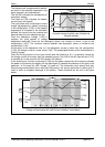
The installation cabling must take this particular function into account, which allows a current
equivalent to the sum of all power outputs in the inverter and the AC source to be available at the
output.
If you have, for example, a 5 kW (22 A) source and an Xtender of 5 kW, the power available at
the output will be 10 kW. The downstream cabling must therefore be dimensioned accordingly. In
this example, the output cable must be dimensioned to support a current of 45 A. A dimensioning
table, fig. 1a, will help you to determine the output currents that dimension the protection devices
and the cable sections to be applied.
The Xtender can supply up to 10x the limit value of the input current {1107}.
If the extender is connected to a generator, this must have a power at least equal to half
of the power of the Xtender(s) to which it is connected.
6.2.8
X
TENDER PROTECTION
The Xtender is protected electronically against overloads, short-circuit, overheating and reverse
current (cabling of a voltage source on AC out).
The battery is protected in all cases against deep discharge. The indicator (52) flashes once
when the battery has reached the disconnection threshold {1108} and the inverter will stop some
time after {1190}. This threshold can be corrected dynamically depending on the instantaneous
power supplied by the inverter if the configuration {1191} is activated. In this case the value of the
dynamic correction is set by the parameter {1109}. The inverter will stop immediately if a critically
low voltage value set by the configuration {1188} is reached. The inverter will restart automatically
when the battery voltage has reached the restarting threshold {1110}.
If the inverter is repeatedly encountering this situation {1304} in a short period {1404}, it will stop
permanently and will only start again via an operator’s manual control.
In the event of overload or short-circuit at the output, the inverter stops for some seconds and
restarts. If the inverter is repeatedly encountering this situation {1300} in a short period, it will
stop permanently and will only start again via an operator’s manual control.
If the battery voltage exceeds the value set by the configuration {1121}, the inverter stops and
starts up again when the voltage is less than {1110}. If the Xtender is repeatedly encountering
this situation {1303} in a short period {1403}, it will stop permanently and will only start up again
via an operator’s manual control.
A battery voltage greater than 1.66 x the nominal voltage may lead to significant damage
or destroy the device.