


Steca Xtender
Installation and Operating Instructions 723.932 Xtender V0.511 Seite 32
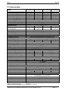
Elem.
Description Comment
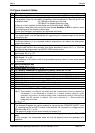
A Input supply
cable
The section is determined by means of the maximum current at
source and the protection device (H). In multi-unit systems, cables
(A) of the same phase must have the same length and section (see
comment fig. 12-2/3).
B Output supply
cable
In multi-unit systems, cables (B) of the same phase must have the
same length and section (see comment fig. 12-2/3). The section
must be selected by means of the Xtender’s output current given
on the type plate and the protection device selected for the input
(see fig. 1a).
C Connection of the
neutrals
See chapter 4.2 - p. 10.
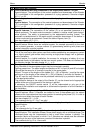
In a fixed installation where the neutral is connected to the earth at
a single installation point upstream of the Xtender, it is permissible
to carry out a connection of the neutrals in order to preserve an
unchanged earthing system downstream, independent of the
operating mode of the Xtender. This choice shows the advantage
of keeping the differential protection devices downstream of the
Xtender.
This connection (C) is not permitted if a socket is installed
upstream of the Xtender.
D Differential circuit
breaker
A protection device must be installed downstream of he source (G
or U) according to the local requirements and in compliance with
the applicable regulations and standards.
E Earth-neutral
connection bridge
The neutral is earthed at a single point of the installation,
downstream of the source and upstream of the protection device(s)
at the default current (DDR). When several sources are available,
each source must have an earthed neutral. If the source has to be
retained with an isolated earthing system (IT) the applicable local
provisions and regulations must be applied.
F AC output
protection
devices for the
Xtender
A protection device dimensioned in dependence of the cable
section used may be installed downstream of the Xtender (main
circuit breaker before distribution). The cable section is to be
dimensioned according to the calculation table of maximum output
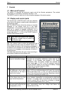
current (fig. 1). The Xtender has an internal current limitation the
value of which is stated on the type plate (35).
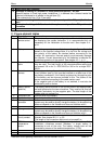
G Generator The generator is dimensioned according to the requirements of the
user. Its rated current will determine the configuration adjustment
{1107} “maximum current of the AC source”.
H Protection
devices at the
Xtender input
The protection device at the input of the Xtender must be
dimensioned according to the power output of the source at the
cable section used. It will not exceed a calibre equivalent to the
input current “I AC in” given on the type plate of the unit (35).
J
K Connection plug /
socket
If the Xtender is connected to an AC source by means of a plug,
the connection cable must not exceed a length of 2 m, and the
socket must remain permanently accessible. The socket will be
protected by a protection device of appropriate calibre. The
connection of the neutrals (C) is prohibited in this case.
L
P
R
S Secured grid Distribution to the users supplied by the grid or the generator when
this is present or by the Xtender within the limit of its power output
from energy stored in the battery. This distribution is carried out in
conformity with the local standards and regulations.