


STUDER Innotec Xtender
Installation and operating Instructions Xtender V1.3 Page 11
This connection (C) is not permitted if a socket is installed upstream of the Xtender.
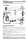
4.2.3
I
NSTALLATION WITH AUTOMATIC
PE-
NEUTRAL SWITCHING
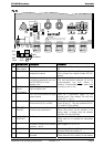
In certain applications, it is desirable to keep the neutral upstream and downstream of the Xtender
separated (C) while reestablishing the earthing system (TN-S, TT or TNC-S) in the absence of
voltage at the input. This can be programmed by the configuration {1485} via the RCC-02/03
remote control. This modification must be carried out possessing technical knowledge, at the
responsibility of the installer and in conformity with the applicable regulations and standards.
This allows adherence to the requirements for an earth-neutral connection at the source.
4.3 Recommendations for dimensioning the system
4.3.1
D
IMENSIONING THE BATTERY
The battery capacity is dimensioned according to the requirements of the user – that is 5 to 10 times
its average daily consumption. The discharge depth of the battery will therefore be limited and the
service life of the battery will be extended.
On the other hand, the Xtender must have a battery capacity that is large enough to be able to take
full advantage of the performance of the equipment. The minimum capacity of the batteries
(expressed in Ah) is generally dimensioned in the following way: five times the rated power output of
the Xtender / the battery voltage. For example, the model XTH 8048 must have a battery of a
minimum capacity of 7000*5/48=730 Ah (C 10). Because of the inverter’s extreme overload capacity,
it is often recommended that this value be rounded up. An under-dimensioned battery may lead to
an accidental and undesired stopping of the Xtender in the event of high instances of use. This
stoppage will be due to a voltage that is insufficient on the battery, subject to a strong discharge
current.
The battery will be selected with regard to the greatest value resulting from the calculations set out
above.
The battery capacity determines the adjustment of the configuration {1137} “battery charge current”.
A value between 0.1 and 0.2 x C batt. [Ah] (C10) enables an optimum charge to be guaranteed.
The method proposed below is strictly indicative and in no way constitutes a guarantee of
perfect dimensioning. The installer is solely responsible for good dimensioning and
installation
4.3.2
D
IMENSIONING THE INVERTER
The inverter is dimensioned in such a way that the rated power output covers the power of all the
consumers which will be used at the same time. A dimensioning margin of 20 to 30% is
recommended to guarantee that the Xtender will work well in an ambient temperature of more than
25 °C.
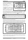
4.3.3
D
IMENSIONING THE GENERATOR
The power output of the generator must be the same or more than the average daily power.
Optimally, it should be two or three times this power. Thanks to the smart boost function it is not
necessary to over-dimension the generator. Indeed, the loads those are temporarily higher than the
power of the generator will be supplied by the inverter. Ideally it should not have a power output by
phase that is less than half of the power of the Xtender(s) present at this phase.
The power available downstream of the inverter when the generator is working is the same
as the sum of the two powers.